Weller WRK User Manual
Page 4
4-9
WRK
Note Also read and observe the Operating Instructions of your control
unit.
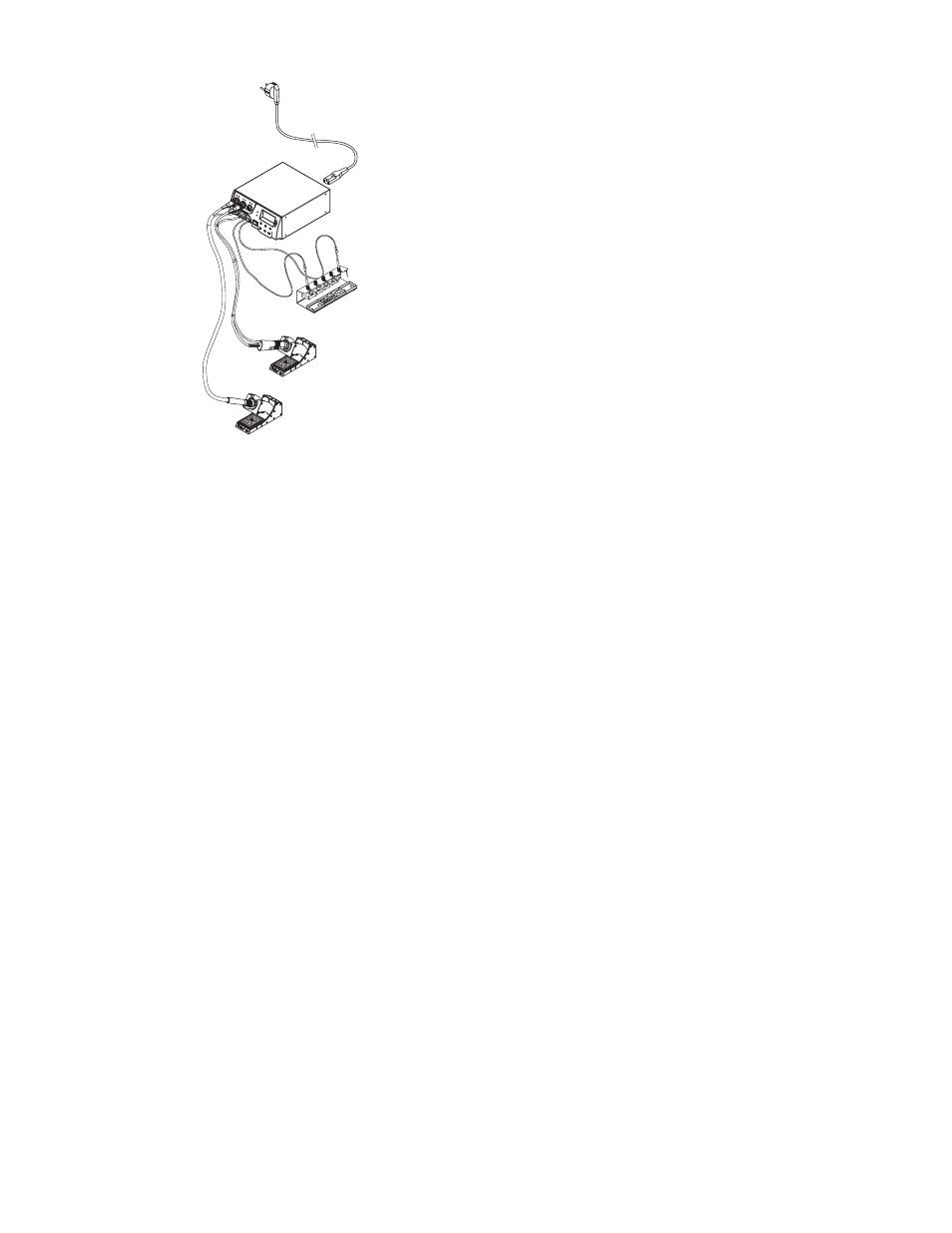
1. Carefully unpack the WRK.
2. Assemble reflow nozzles (2, 3), tripod (4) and pick-up tool (6) in
holder (1).
3. Switch off the control unit.
4. Connect the hot-air pencil (HAP) with air hose to the "Air“ outlet of
the control unit and insert with the attachment plug in the correct
connection socket of the repair station. Lock by turning clockwise
slightly (connect HAP 1 with adapter only).
5. Connect vacuum pick-up (6) with vacuum hose to the vacuum
pick-up ports of the control unit.
6. Attach a suitable reflow nozzle or tripod to the vacuum pick-up
(see Sections 5.1 and 5.2).
It is possible to use large reflow nozzles, small reflow nozzles with
tripod or the tripod on its own to lift off small components with the
vacuum pick-up tool.
4.1 Mounting the Reflow Nozzle
1. Check the .400 ", (10 mm) diameter vacuum pick-up tool to ensure
the components (clamping sleeve (5), marker ring (7) and vacuum
cup with heat shield (10)) are correctly installed.
2. Assemble nozzles directly to vacuum pick-up tool (6) using the
clamping sleeve (5).
Note The reflow nozzles are not assembled directly to the .180 ", (4.5
mm) vacuum pick-up tool. Ensure the tripod and the.180 ", (4.5 mm)
diameter vacuum pick-up tool are correctly positioned in the nozzle
and on the component.
4.2 Mounting the tripod
1. Check the .180 ", (4.5 mm) diameter vacuum pick-up tool to
ensure the components (clamping sleeve (5), marker ring (7) and
vacuum cup with heat shield (10)) are correctly assembled.
2. Screw tripod (4) to the vacuum pick-up tool (6) using the clamping
sleeve (5).
You can use the .180 ", (4.5 mm) diameter vacuum pick-up tool
mounted in this way with a Large reflow nozzle (A1) or with Small a
reflow nozzle (B1). When working without a reflow nozzle, you can
also use a .400 " (10 mm) diameter vacuum pick-up tool.