5 using the wrk – Weller WRK User Manual
Page 5
WRK
5-9
EN
FR
IT
ES
PT
NL
SV
DK
FI
GR
TR
CZ
PL
HU
SK
SL
EE
LV
LT
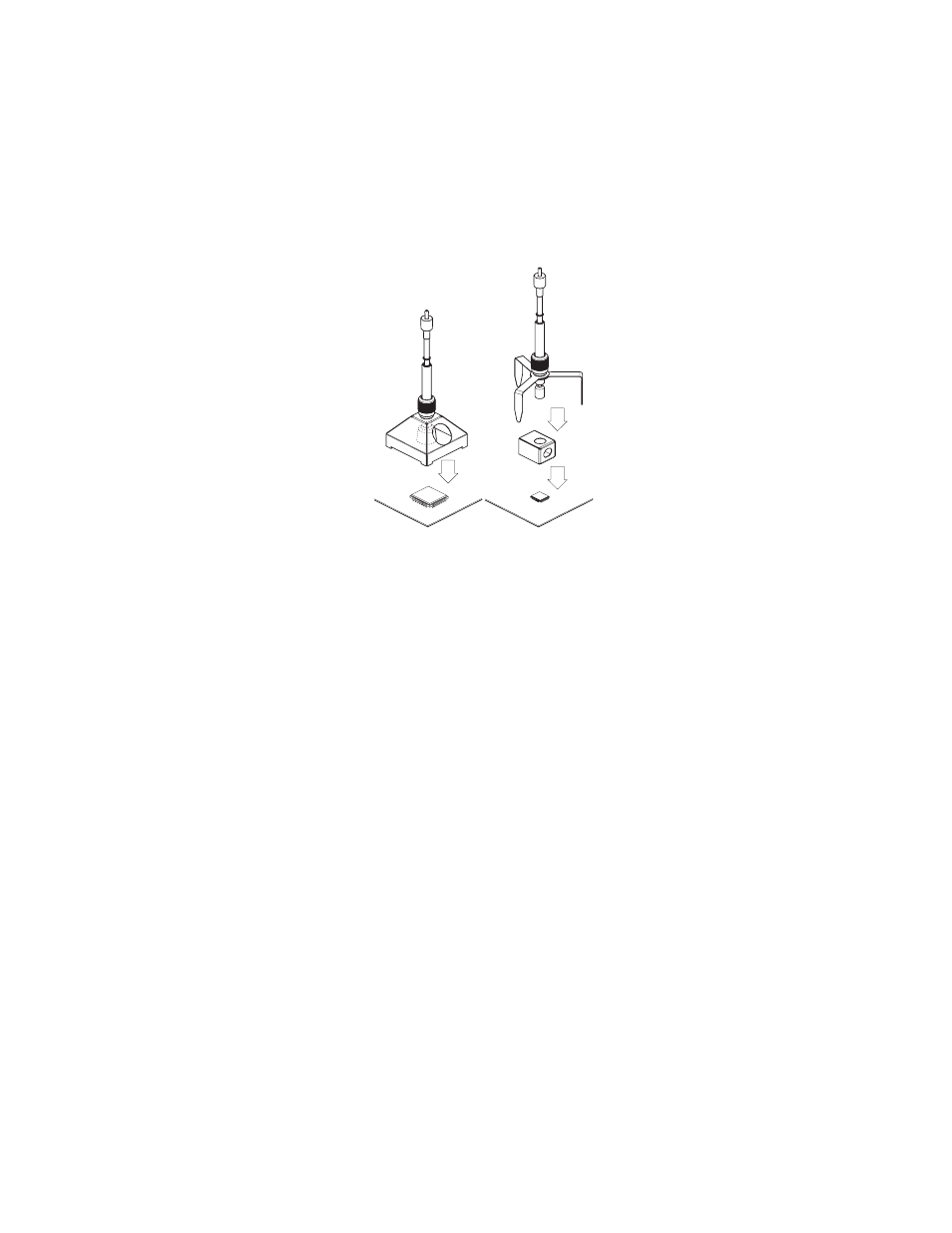
A 1
B 1
5 Using the WRK
WRK operation during the component removal procedure is divided
into 3 steps:
1. Positioning the Vacuum Pick-up tool
2. Preparing for Component Pick-up
3. Reflow and Removal of the component
5.1 Positioning the Pick-up
The component to be reworked must be at least .08 " , (2 mm)
smaller than the diameter of the reflow nozzle used, otherwise the
component may be damaged.
Z
Carefully position the large reflow nozzle (A1) or tripod with small
reflow nozzle (B1) with the vacuum pick-up tool over the
component and center the component within the nozzle.
See also other documents in the category Weller Tools:
- WDH 10T (7 pages)
- HAP 200 (6 pages)
- 6966 HEAT GUN (5 pages)
- BP645MP (2 pages)
- BP860MP (2 pages)
- D650 (4 pages)
- DEC1001 (4 pages)
- DS800 (4 pages)
- DTL1000 (3 pages)
- EC1302B (2 pages)
- EC2002M (4 pages)
- ML100 (1 page)
- ML200 (1 page)
- ML500MP (1 page)
- MT1500L (4 pages)
- Cordless Soldering Tool (2 pages)
- WHA 30 P (14 pages)
- TB100PK (2 pages)
- WA2000 (9 pages)
- WCB1 (2 pages)
- WD2M (22 pages)
- WES50 (4 pages)
- WES51 (7 pages)
- WESD51 (7 pages)
- WHA900 (11 pages)
- WHP 3000 (37 pages)
- WLC100 (3 pages)
- WLC200 (2 pages)
- WSB25 (21 pages)
- WQB2000 (9 pages)
- WR2 (65 pages)
- WR 3M (21 pages)
- WS80 (3 pages)
- WSD130 (6 pages)
- WSD80 (6 pages)
- WTCPT (4 pages)
- WTL1000S (5 pages)
- WX2 (128 pages)
- WXMP (72 pages)
- WX120 (56 pages)