Installation of bushings, Pump assembly, Carbon graphite – Viking Pump TSM635.2: K-LS Universal Mag Drive User Manual
Page 7: Danger, Caution
SECTION TSM
635.2
ISSUE
E
PAGE 7 OF 12
INSTALLATIoN oF BUSHINGS
CARBoN GRAPHITE
The canister bushing requires a special fixture for proper
assembly so the bushing is only sold as part of the canister
assembly.
If attempting to install the carbon graphite idler or adaptor
plate bushings, extreme care must be taken to prevent
breaking. Carbon graphite is a brittle material and easily
cracked. If cracked, the bushing will quickly disintegrate.
Using a lubricant on the bushing and mating part will help
facilitate installation.
3. Screw the end cap into the bracket (clockwise) until it
contacts. Do not over-tighten the end cap.
4. Inspect the outer magnet to make sure it has not picked
up any foreign particles, which could damage the pump.
Slide the inner roller bearing onto the shaft, followed by
the inner bearing spacer.
5. Slide the outer magnet assembly into the bracket. Slide
the outer roller bearing onto the shaft. Slide the outer
bearing spacer collar onto the shaft and into the outer
lipseal, followed by the lockwasher and locknut.
6. Tighten the locknut to 120-140 ft-lbs of torque and then
bend over the appropriate lockwasher tab.
7. Unscrew the end cap (counterclockwise) by hand until
there is considerable drag on the bearings. Mark the end
cap and bracket in the same spot. Then screw in the end
cap (clockwise) 5/16”, radially from the mark. Tighten the
end cap setscrews.
8. Grease the bracket using the bracket fitting with NLGI #2
grease. Make sure the shaft freely rotates by hand.
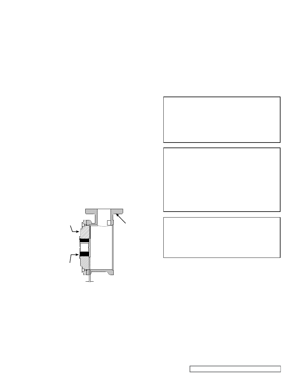
FIGURE 10
ADAPToR PLATE BUSHING PoSITIoN
ADAPToR
PLATE
CASING
BUSHING
INCH MM
.245 6.223
.242 6.147
1. If the adaptor plate O-ring needs to be replaced, apply a
lubricant to the O-ring and place it onto the casing side
of the plate adaptor. If the O-ring is PTFE (derivative)
encapsulated, follow these special instructions.
Do not attempt to reuse this type of O-ring if it has been
removed. Immerse a new O-ring in boiling water for a
few minutes. Remove it from the water and stretch out
the O-ring. This ensures it will fit into the plate or groove
without forcing the O-ring over a sharp edge. Run hot
water over the O-ring until it shrinks down tight. Hot water
makes the PTFE pliable and allows the inner elastomer
to pull the PTFE back to the original size. Dry it with
compressed air.
2. Position the adaptor plate so the adaptor plate groove
aligns to groove in the casing bore at Port B, see
Figure
11 on page 8 (The adaptor plate in the K & KK models
have a single groove, the L-LS models have a groove and
two machined relief pockets.) Carefully slide the plate
DANGER !
Follow these directions exactly to avoid injury
to self or damage to the pumping unit. Be
careful to keep the inner and outer magnets at
least (1) foot apart until step 14. Do not engage
the magnets in any other fashion.
CAUTIoN !
Do not place fingers onto the front of pump
mounting flange. Align the canister into bore
of the bracket and gently slide it in. When the
magnets start to engage, the unit will finish
engagement on its own very rapidly unless the
1/2” x 5” capscrew is properly used. Make sure
fingers are not on the front of the pump. See
Sequence in Figure 13.
PUMP ASSEMBLY
DANGER!
Be certain that the driving means (motor, tur-
bine, engine, etc.) has been “locked out” or
made non-operational so that it cannot be
started while work is being done on pump.
The groove in the ID of the bushing should line up with the
groove in the adaptor plate.
Figure 10 shows the proper
position of the adaptor plate bushing after installation. This
may require a special fixture to ensure proper positioning.
Improper location may result in a pump with excessive slip,
pre-mature wear or requiring a large number of shims. The
additional precautions listed below must be followed for
installation:
1. An arbor press must be used for the installation.
2. Be certain the bushing is started straight.
3. Do not stop the pressing operation until the bushing is in
the proper position; starting and stopping will result in a
cracked bushing.
4. After installation, check the bushing for cracks.
Use a suitable lubricant compatible with the fluid being
handled when reassembling the pump.
Inspect all parts, especially drilled holes in the casing (for
draining) to make sure they are not plugged. Replace any
worn parts, remove any burrs and clean all parts before
assembling the pump.