Maintenance, Caution – Viking Pump TSM635.2: K-LS Universal Mag Drive User Manual
Page 3
SECTION TSM
635.2
ISSUE
E
PAGE 3 OF 12
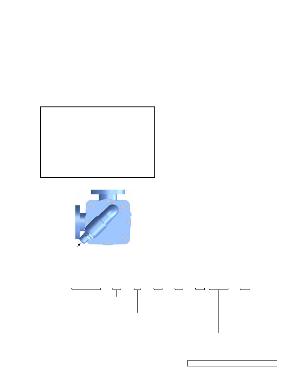
FIGURE 2 RELIEF VALVE PoSITIoN
CAUTIoN !
Rare earth magnets used in couplings have
extremely strong magnetic fields capable of
changing performance or damaging items
such as the following:
Pacemakers
Metal Implants
Watches
Computers & disks
Credit Cards
RELIEF VALVE ADJUSTING SCREW CAP
SUCTIoN
DISCHARGE
MAINTENANCE
Series 8124A, 8123A and 8127A pumps are designed
for long, trouble-free service life under a wide variety of
application conditions with a minimum of maintenance. The
points listed below will help provide long service life.
CLEANING PUMP:
Keep the pump as clean as possible. This will facilitate
inspection, adjustment and repair work.
LUBRICATION:
Bracket bearings require external lubrication. This must be
applied slowly with a handgun to lubrication fittings every
500 hours of operation with multi-purpose grease, NLGI
# 2. Do not over-grease. Applications involving very high
or low temperatures will require other types of lubrication.
Refer to ESB-515. Consult factory with specific lubrication
questions.
STORAGE:
If the pump is to be stored, drain and pour non-detergent
SAE 30-weight oil (or compatible alternative) into the pump
port. Apply grease to the pump shaft, if present or accessible.
Viking suggests rotating the pump shaft every 30 days to
circulate the oil in the pump. The pump should be stored in
a dry area.
SUGGESTED REPAIR TOOLS:
The following tools are required to properly repair Series
8124A, 8123A and 8127A pumps. These tools are in addition
to standard mechanics’ tools such as open-end wrenches,
pliers, screwdrivers, etc. Most of the items can be obtained
from an industrial supply house.
1. Soft face hammer
2. Allen wrench set (SAE)
3. Torque wrench with a locknut socket
4. Two feeler gauge sets
5. Arbor press
6. Brass bar
7. Hook style spanner wrench
2. Relief valves are mounted as standard on the casing of
all pumps.
3. If the pump rotation is to be reversed during operation,
pressure protection must be provided on both sides of
the pump.
4. The relief valve adjusting screw cap must always point
towards the suction side of the pump, see
Figure 2. If
the pump rotation is reversed, remove the pressure relief
valve and turn end for end (see
“Pump Rotation”, page
9).
5. Pressure relief valves cannot be used to control pump
flow or regulate discharge pressure.
For additional information on pressure relief valves, refer to
Technical Service Manual TSM000 and Engineering Service
Bulletin ESB-31.
L S 8 1 2 4 A-325 R
Jacketing:
1 = Non-Jacketed
Bracket
Shaft Sealing:
8 = Sealless
Material of Construction:
3 = Steel Externals
4 = Cast Iron
7 = Stainless Steel
Size:
K
KK
L
LQ
LL
LS
Series Edition:
A = Original
Design
Drive Configurations:
__ = Standard Pump
D = Direct Drive
R = Reducer Drive
P = Purchased Reducer
Torque Specifications:
K-KK = 90 Ft-lb
K-KK = 180 Ft-lb
L-LS = 325 Ft-lb
2 = Bearing
Shaft Support
Field 1
Field 2
Field 3
Field 4
Field 5
Field 6
Field 7
Field 8
Field 9
FIGURE 3
MoDEL NUMBER SYSTEM