Viking Pump TSM635.1: H-HL Universal Mag Drive User Manual
Page 8
SECTION TSM
635.1
ISSUE
E
PAGE 8 OF 12
FIGURE 12
SETTING THRUST WASHER CLEARANCE
8. Tighten the setscrew in the locknut. Check the feeler
gauges. If the gauges are too tight, loosen the setscrew
and locknut slightly and repeat tightening procedure.
Remove the feeler gauges. Check to make sure the pump
rotates freely by turning the inner magnet assembly.
9. Inspect the magnet to make sure it has not picked up
any foreign particles, which could damage the pump.
Inspect the canister bushing; replace if needed. See
“Installation of Bushings” on page 7. Lubricate the
ID of the canister bushing. Inspect the canister o-ring;
replace if needed. Refer to Step 1 if PTFE (derivative)
encapsulated. Lubricate and place the o-ring into the
groove in the adaptor plate. Align the roll pin in the
adaptor plate with the corresponding hole in the canister
and place the canister onto the shaft. Secure the canister
using eight capscrews.
10. If the old shims are not reusable or if any parts have
been replaced, operating clearances will need to be re-
established. Refer to
“Adjusting End Clearance” on
page 9. Otherwise, place the head shims on the head.
The proper amount of shims should be used to provide
the correct end clearance (0.004” for sizes H-HL).
Inspect the head o-ring; replace if needed. Refer to
Step 1 if PTFE (derivative) encapsulated. Lubricate the
O-ring and place on the head.
11. Coat the ID of the idler bushing with a suitable lubricant
and place the idler on the idler pin in the head.
12. Align the hole in the head, at the base of the idler pin, with
the casing port opposite the groove in the adaptor plate.
Hole will be slightly offset to CCW side of the port.
13. The head can now be assembled onto the pump. Tilt
the top of the pump head away from the pump slightly
until the crescent enters the inside diameter of the
rotor and rotate the idler until its teeth mesh with the
rotor teeth. Secure the head to the casing using six
to eight capscrews. Check the end clearance. Refer
to
“Adjusting End Clearance” on page 9, if needed.
Rotate the shaft by hand to make sure it turns freely.
The pump head and casing should have been marked
before disassembly to insure proper reassembly. If not,
be sure the idler pin, which is offset in the pump head, is
placed between the port connections to allow for proper
flow of liquid through the pump.
14. Inspect the bracket bearings and lipseals; replace
if needed. Refer to
“Disassembly / Assembly of
Bracket Bearings”, page 6. Inspect the outer magnet
for any steel objects, which may be attached. Remove
any foreign material. Secure the bracket to a base or
other stable platform. Rotate the outer magnet shaft by
hand to make sure there is no interference. If rubbing
occurs, visually inspect for debris. Consult the factory if
rubbing between the outer magnet and bracket persists.
15. Insert two fully threaded 5/16” X 4” socket head
capscrews into the bracket until they are fully extended
in front of the bracket to control assembling the pump,
see
Figure 13 on page 9. To keep the pump and bracket
assemblies properly aligned and for additional safety, it
is recommended to use 2 lengths of all-thread rod (6-8”)
threaded into diagonal capscrew locations in the bracket
and slide through the corresponding holes in the adaptor
plate.
THRUST WASHER
FEELER
GAUGES
3. Apply lubricant to the ID of the adaptor plate bushing.
Clean the rotor and shaft so it is free of dirt, grit and other
debris. Remove burrs around the keyway and shoulder
of the shaft.
4. Place one thrust washer onto the shaft so that the blind
hole in the thrust washer will line up with the drive pin
on the back of the rotor. Slide the shaft into the adaptor
plate bushing as far as it will go. Make sure that the
thrust washer remains seated on the drive pin and flat
against the rotor.
5. Slide the second thrust washer onto the shaft, drive hole
facing out. Then install the key into the shaft.
6. Clean the face on the inner magnet that faces the casing.
Slide the inner magnet onto the shaft and engage the pin
of the magnet into the hole of the thrust washer. Install
the split locknut with the raised face out, do not tighten
completely.
7. Place two feeler gauges (0.001”), one on each side,
between the adaptor plate bushing and the inner magnet
thrust washer. Refer to
Figure 12. This will establish
the proper clearance for the thrust washers. Tighten the
locknut until the feeler gauges are snug, but can still be
removed. Do not remove the feeler gauges at this time.
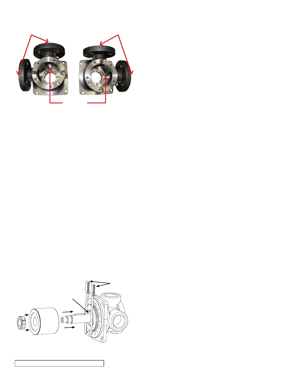
FIGURE 11
ADAPToR PLATE / CASING PoSITIoNING HL SIZE
SHoWN
VIEWED FRoM HEAD END
ADAPToR
PLATE GRooVE
CASING
PoRTS
CASING
PoRTS