Pressure relief valve instructions, Disassembly – relief valve, Danger – Viking Pump TSM635.1: H-HL Universal Mag Drive User Manual
Page 10: Assembly – relief valve
SECTION TSM
635.1
ISSUE
E
PAGE 10 OF 12
FIGURE 16
PRoCEDURE B
PRoCEDURE B
If the pump is in line and ports are not accessible, remove the
head and shims. Put the head back on (without shims) and
measure the gap as shown, see
Figure 16. After determining
the gap between the head and casing, select a combination
of shims equal to the measured gap plus the desired end
clearance. Remove head, install shims then install head.
Tighten the head capscrews and check the pump clearance
by making sure the pump turns freely by hand.
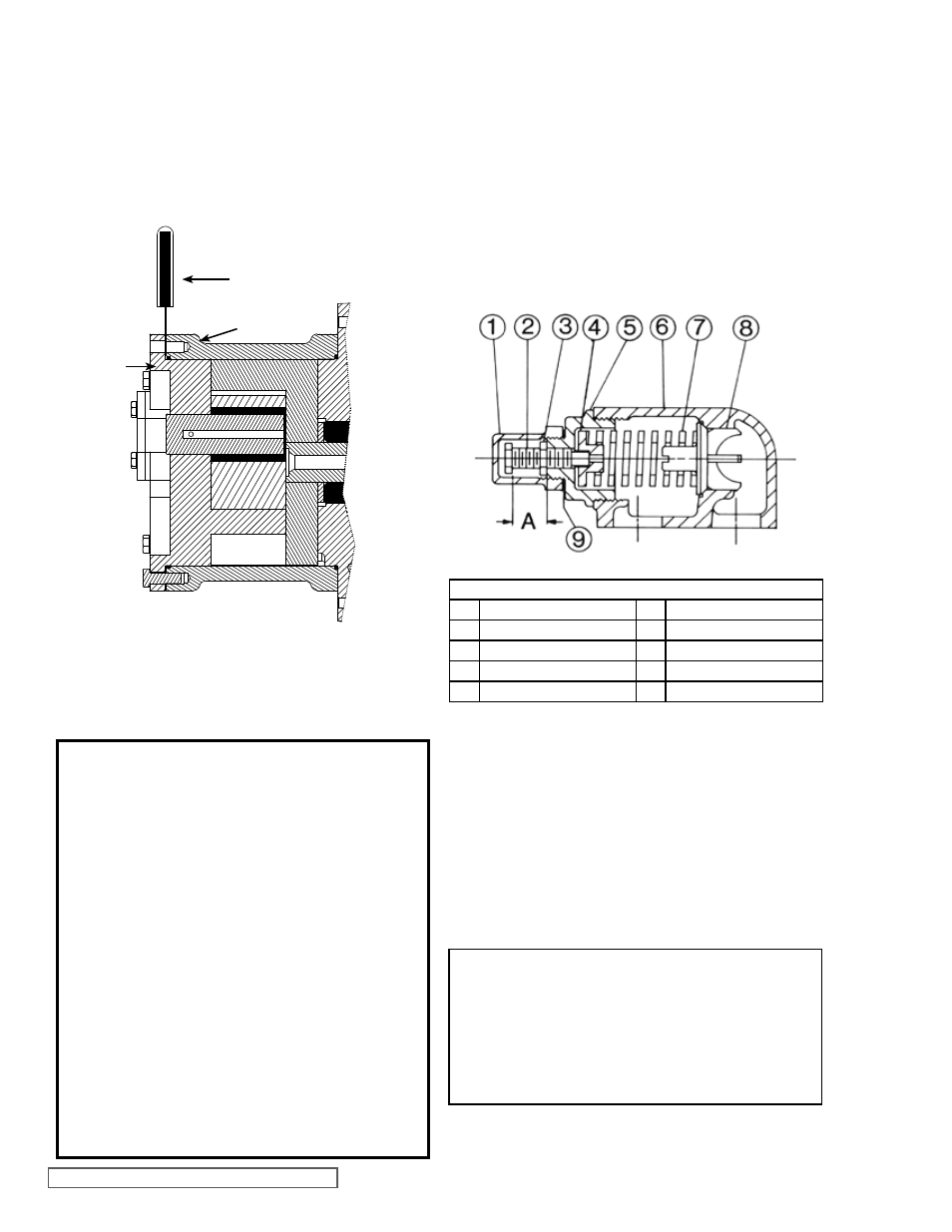
FIGURE 17
VALVE – H AND HL SIZES
VALVE - LIST OF PARTS
1. Valve Cap
6. Valve Body
2. Adjusting Screw
7. Valve Spring
3. Lock Nut
8. Poppet
4. Spring Guide
9. Cap Gasket
5. Bonnet
DISASSEMBLY – RELIEF VALVE
Mark the valve and head before disassembly to insure
proper reassembly.
1. Remove the valve cap.
2. Measure and record the length of extension of the
adjusting screw. Refer to
“A” on Figure 17.
3. Loosen the locknut and back out the adjusting screw
until spring pressure is released.
4. Remove the bonnet, spring guide, spring and poppet
from the valve body. Clean and inspect all parts for wear
or damage and replace as necessary.
DANGER!
Before starting pump, be sure all drive equip-
ment guards are in place.
Failure to properly mount guards may result in
serious injury or death.
PRESSURE RELIEF
VALVE INSTRUCTIoNS
ASSEMBLY – RELIEF VALVE
Reverse the procedures outlined under
DISASSEMBLY
– RELIEF VALVE. If the valve is removed for repairs, be sure
to replace in the original position. The relief valve adjusting
screw cap must
always point towards the suction side of
the pump. If the pump rotation is reversed, remove the relief
valve and turn end for end. Refer to
Figure 2, page 3.
FEELER GAUGE
CASING
HEAD
DANGER !
Before opening any Viking pump liquid cham-
ber (pumping chamber, reservoir, relief valve
adjusting cap fitting etc.) Be sure:
1. That any pressure in the chamber has been
completely vented through the suction
or discharge lines or other appropriate
openings or connections.
2. That the driving means (motor, turbine,
engine, etc.) has been “locked out” or made
non- operational so that it cannot be started
while work is being done on pump.
3. That you know what liquid the pump has been
handling and the precautions necessary to
safely handle the liquid. obtain a material
safety data sheet (MSDS) for the liquid to be
sure these precautions are understood.
Failure to follow above listed precautionary
measures may result in serious injury or death.