Disassembly / assembly of bracket bearings, Disassembly, Assembly – Viking Pump TSM635.1: H-HL Universal Mag Drive User Manual
Page 6
SECTION TSM
635.1
ISSUE
E
PAGE 6 OF 12
9. Visually inspect the outer magnets from the end of the
bracket. If removal is necessary, separate the bracket
from the motor. Remove the locknut (1), lockwasher (2)
and outer bearing spacer collar (4) from the shaft. Slide
the outer magnet assembly out of the bracket. Inspect
the magnet assembly for damage or wear; replace
if needed. If further disassembly of the bracket is
required, see
“Disassembly / Assembly of Bracket
Bearings”.
10. Remove the socket head capscrews (54) from the
canister (59). If the canister was not drained in Step
1, it will contain liquid. Use care when removing the
canister from the pump by pulling it straight off. Inspect
the canister bushing (64) for wear. If the canister
bushing needs to be replaced, see
“Installation of
Bushings” on page 7.
11. Do not remove the O-ring from the plate adaptor
(67) / canister unless it is bad, especially if it is PTFE
(derivative) encapsulated. If a new O-ring is required,
See
“Pump Assembly” on page 8.
12. Insert a brass bar into the rotor (36) through a port
between two rotor teeth and remove the split locknut
(66), see
Figure 8. Slide the inner magnet assembly
off of the shaft. Make sure the outer thrust washer (60)
does not come off with the inner magnet assembly. If
the thrust washer hits the shaft key (62) it may crack
or break. Do not forget this is a very strong magnet.
Inspect the magnet assembly for damage or wear;
replace if needed. If further disassembly is required,
proceed to the next step.
FIGURE 8
INNER MAGNET AND LoCKNUT ASSEMBLY
DISASSEMBLY / ASSEMBLY oF
BRACKET BEARINGS
DISASSEMBLY
The bracket bearing assembly features two tapered roller
bearings, two lipseals, and one spacer. If further disassembly
of this unit is required, proceed as follows:
1. Loosen the setscrews holding the end cap (3) in the
bracket. Screw the end cap out of the bracket.
2. Inspect the bearings (6) for wear; replace as needed.
3. Inspect the lipseals (5) for wear; replace as needed. The
lipseals will need to be replaced if removed.
4. If the bearings are worn it is recommended to replace
the entire bearing. Remove the inner bearing spacer
collar (8). Press the inner bearing cup (6) out of the
bracket and the outer bearing cup out of the end cap.
The bearings will need to be replaced if the cups are
removed.
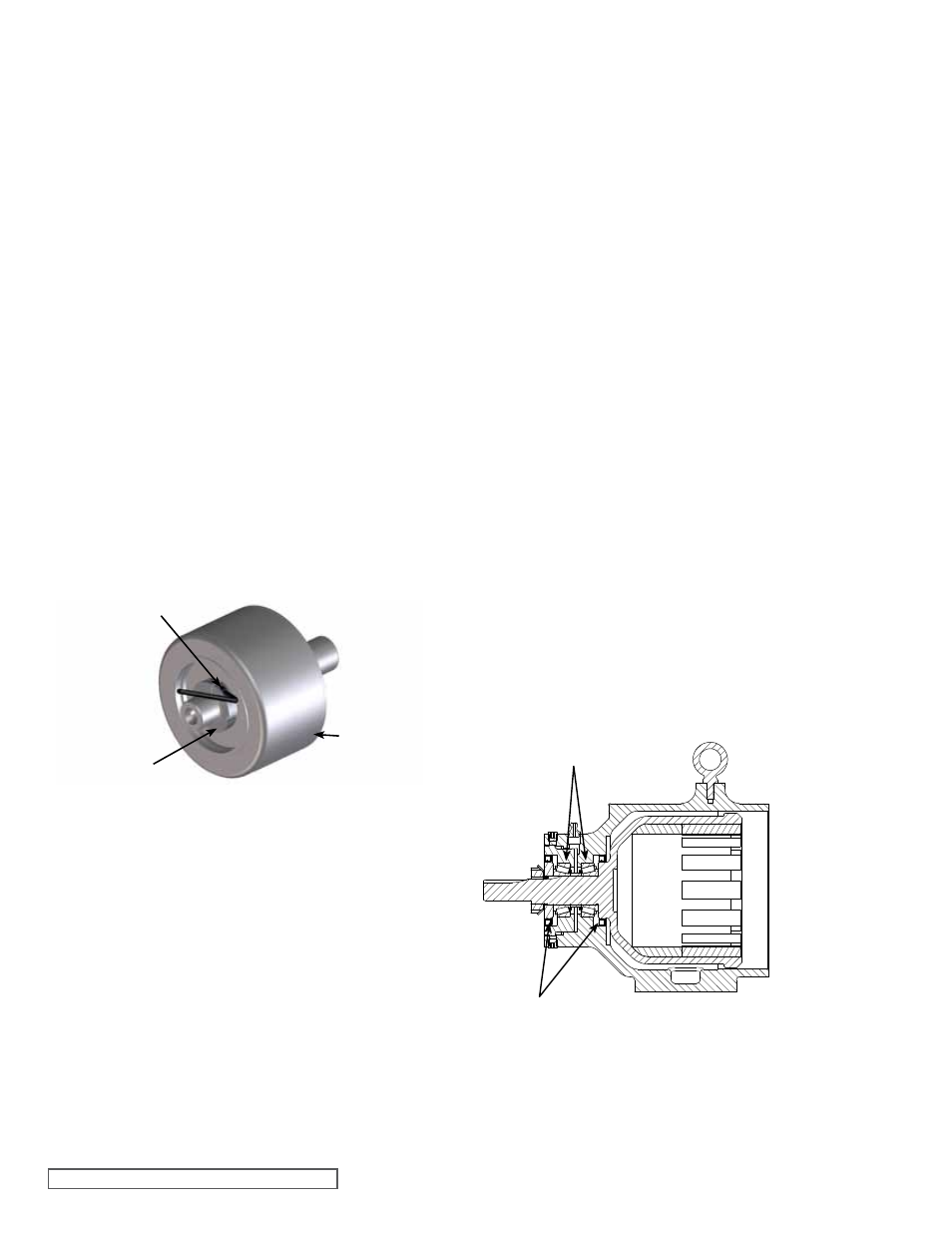
ASSEMBLY
1. If the bearing cups were removed, press the cup of the
outer bearing into the end cap. Press the cup of the inner
bearing into the bracket.
2. Press the inner lipseal into the bracket and the outer
lipseal into the end cap and then lubricate the lipseals,
see
Figure 9 for lipseal and bearing orientation.
FIGURE 9
BRACKET BEARING AND LIPSEAL oRIENTATIoN
SETSCREW
LoCKNUT
INNER
MAGNET
ASSEMBLY
TAPERED RoLLER BEARINGS
LIPSEALS
13. Remove the shaft key from the rotor shaft. Remove
the outer thrust washer. The rotor and shaft (36) may
now be removed by tapping on the end of the shaft
with a soft face hammer (If a soft face hammer is not
available a regular hammer may be used with a piece of
hardwood). Remove the inner thrust washer from behind
the rotor. Check the thrust washers for cracks or wear;
replace if necessary.
14. Inspect the adaptor plate bushing. If the bushing needs
to be replaced, see
“Installation of Bushings”, page
7. Remove the socket head capscrews (13) from the
adaptor plate. Slide the adaptor plate out of the casing.
15. Do not remove the O-ring from the plate adaptor / casing
unless it is bad, especially if it is PTFE (derivative)
encapsulated. If a new O-ring is required, See
“Pump
Assembly” on page 7.
16. Inspect the casing for wear, particularly in the area
between the ports. Clean all other parts thoroughly and
examine for wear or damage.
When making major repairs, such as replacing a rotor and
shaft, it is advisable to also install a new head and idler
pin, idler and bushing, and adaptor plate bushing. See
“Installation of Bushings” on page 7.
3. Screw the end cap into the bracket (clockwise) until it
contacts. Do not over-tighten the end cap.
4. Inspect the outer magnet to make sure it has not picked
up any foreign particles, which could damage the pump.