Unit installation, Harmful situation, Nord gear corporation – Viking Pump NORD TSM For NORDBLOC.1 Reducers User Manual
Page 6: Nord gear limited, Retain for future use
DRIVESYSTEMS
UNIT INSTALLATION
RETAIN FOR FUTURE USE
U10060 - 1 of 2
1. Installation site
Drives must be properly installed if they are to produce the
rated torque. Improper installation may lead to oil leaks, re-
duced life, or even catastrophic failure. NORD gear drives
and motors are intended to be installed at a suitable mount-
ing site under the following conditions:
t 6OJNQFEFEBJSnPXUPBOEBSPVOEUIFVOJUT
t "DDFTTJCJMJUZUPPJMESBJO
MFWFMBOECSFBUIFSQMVHT
t 0OCSBLFNPUPST
BMMPXBEFRVBUFTQBDFGPSSFNPWJOHUIF
fan guard and replacing and adjusting the brake.
t .PVOUJOH TVSGBDFT NVTU CF nBU
UPSTJPOBMMZ SJHJE
BOE
dampened against vibration.
t 6OMFTTTQFDJBMNFBTVSFTBSFUBLFO
UIFJNNFEJBUFWJDJOJUZ
around the gear drive or motor should not be exposed
to any aggressive or corrosive substances, contaminated air,
ozone, gases, solvents, acids, alkalis, salts, radioactivity, etc.
2. Mounting position
Reducer mounting position charts illustrate the standard
mounting positions for horizontal and vertical mounting.
"MMHFBSVOJUTBSFBTTFNCMFEXJUIUIFPJMmMMMFWFM
PJMESBJO
and vent plugs installed in their proper locations, according
to the customer-specified mounting position. For mounting
orientations other than shown consult NORD Gear.
STOP
HARMFUL SITUATION
STOP
The gear reducer may not receive proper lubrication if
the unit is not mounted in the position for which it is
designed. Observe the mounting position designated
PO UIF SFEVDFS OBNFQMBUF
PS TQFDJmFE JO UIF PSEFS
acknowledgement. Consult NORD prior to changing
NPVOUJOHQPTJUJPOJOUIFmFME8IJMFJUJTPGUFOQPTTJCMF
UP TJNQMZ SFMPDBUF UIF PJM mMMMFWFM BOE WFOU MPDBUJPOT
BOEBEKVTUUIFPJMmMMBNPVOU
JOTPNFDBTFT
EJGGFSFOU
mounting positions may lend themselves to different
internal construction features.
3. Reducer mounting
t 5IFTVQQPSUGPVOEBUJPONVTUCFTUSBJHIU *FWFMBOEnBU
8IFUIFS UIF HFBS VOJU JT GPPUNPVOUFE PS nBOHF
mounted, NORD recommends that the straightness and
nBUOFTT PG UIF DVTUPNFSTVQQMJFE TVQQPSU GPVOEBUJPO
follow Table 1.
t 5IF HFBS VOJU NVTU CF QSPQFSMZ BMJHOFE XJUI UIF ESJWFO
shaft of the machine in order to prevent additional
stress or load forces from being imposed upon the gear
unit.
t 5P GBDJMJUBUF PJM ESBJOBHF JU NBZ CF EFTJSBCMF UP FMFWBUF
the gear box foundation above the surrounding
support structure.
t "MM CPMUJOH TVSGBDFT NVTU CF DMFBO BOE GSFF GSPN
contamination and corrosion.
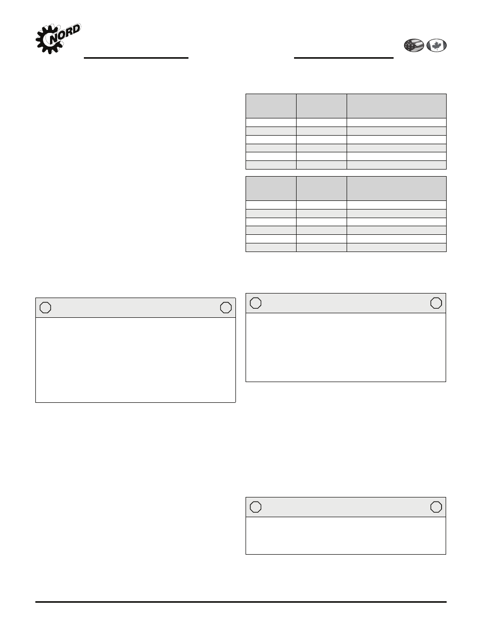
Table 1: Recommended Straightness and Flatness of
Customer-Supplied Support Foundation
Above
(in)
To &
Including
(in)
General Tolerance on
Straigtness & Flatness
ISO 2768-2, Tolerance Class K
0.00
0.39
+/- 0.002 in
0.39
1.18
+/- 0.004 in
1.18
3.9
+/- 0.008 in
3.9
11.8
+/- 0.016 in
11.8
39
+/- 0.024 in
39
118
+/- 0.031 in
Above
(mm)
To &
Including
(mm)
General Tolerance on
Straigtness & Flatness
ISO 2768-2, Tolerance Class K
0
10
+/- 0.05 mm
10
30
+/- 0.1 mm
30
100
+/- 0.2 mm
100
300
+/- 0.4 mm
300
1000
+/- 0.6 mm
1000
3000
+/- 0.8 mm
Straightness: Based upon the length of the corresponding line.
Flatness: Based upon the longer lateral surface or the
diameter of the circular surface.
STOP
HARMFUL SITUATION
STOP
The responsibility for the design and construction of the
support foundation is with the user. The foundation
must be adequate to withstand normal operating loads
and possible overloads while maintaining alignment to
attached system components under such loads. Motors
and drive components mounted on prefabricated base
plates can become misaligned during shipment. Always
check alignment after installation
.
4. Steel foundation
"O FOHJOFFSFE TUSVDUVSBM TUFFM GPVOEBUJPO TIPVME CF
designed to provide adequate rigidity and prevent loads
from distorting the housing or causing misalignment of inter-
OBMHFBSTBOETIBGUT8IFOGPPUNPVOUJOHUIFHFBSSFEVDFS
a base plate or sole plate with suitable thickness (generally
equal or greater than the thickness of the drive feet) should
be securely bolted to steel supports and extend under the
FOUJSFHFBSESJWFBTTFNCMZ8IFOnBOHFNPVOUJOHUIFHFBS
unit, the bulk head plate must be engineered to minimize
buckling distortions and support the cantilevered weight of
the gear unit or gear motor.
STOP
HARMFUL SITUATION
STOP
Do not weld on the gear unit or use the gear unit as an
earth or ground connection for any welding procedure
as this may cause permanent damage to the bearings
and gears.
www.nord.com/docs
06.09.09
NORD Gear Corporation
Toll Free in the United States: 888.314.6673
NORD Gear Limited
Toll Free in Canada: 800.668.4378