Installation locating the pump, Equipment, piping and hose, Electrical connections – Viking Pump TSM442: GG-AL 4195-G LP-Gas User Manual
Page 9
SECTION TSM 442
ISSUE
C
PAGE 9 OF 10
INSTaLLaTION
LOCaTINg THE PUMP
The pump should be mounted on a level surface A flat
concrete slab serves very well as a foundation Make sure
that there is a 12” or more vertical distance between the
bottom of the tank and the pump inlet port centerline The
greater the vertical distance between the bottom of the tank
and the pump inlet, the better the pump will perform and the
longer it will last
EQUIPMENT, PIPINg aND HOSE
All equipment, plus the piping, fittings, hose, etc must
be approved for use with LP-Gas The equipment and
installation must meet local standards as well as those of the
National Fire Protection Association (NFPA) Standard No
58 All threaded connections should be coated with a thread-
sealing compound approved for LP-Gas service
ELECTRICaL CONNECTIONS
All electrical hookups should be made by a qualified
electrician and must meet all applicable local and national
standards for installations handling LP-Gas
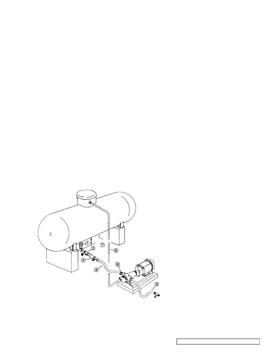
fIgURE 10
TYPICaL INSTaLLaTION Of VIkINg gg 4195D-g
LP-gaS PUMP UNIT SHOWINg RECOMMENDED
EQUIPMENT aND LOCaTION.
1. Excess Flow Valve
2. Shut Off Valve – Full opening type
3. Strainer, 40 mesh; optional
4. Hose, 1”; Maximum length 3 feet
5. Filler Hose, 75” Minimum with shut off valve and
filler connection; 15ft Maximum
6. Return Line, 0 50” Minimum, from by-pass Valve
7. Distance between bottom of tank and pump port
centerline should be at least 12 inches (one foot)
More vertical distance will help pump operate
better and last longer
8. Hydrostatic Relief should be installed in pump
inlet port or in inlet piping
1- 25” Fittings
and pipe
connection
}
12” Minimum