Thrust bearing adjustments, Valve instructions assembly – Viking Pump TSM442: GG-AL 4195-G LP-Gas User Manual
Page 6
SECTION TSM 442
ISSUE
C
PAGE 6 OF 10
7. Pack the lubrication chamber between the casing ball
bearing and the double row ball bearing in the bearing
housing approximately half full with
lithium base ball
bearing grease
8. Pack the double row ball bearing with lithium base ball
bearing grease and press into the bearing housing
Install the snap ring to hold the bearing in place
NOTE: On AS, AK and AL pumps, install the lipseal in
the bearing housing end cap Put the bearing spacer
sleeve in the lipseal and install this in the bearing
housing and tighten securely
9. Start the bearing housing into the casing Turn by
hand until tight This forces the rotor against the head
Replace and tighten the locknut on the shaft Insert a
piece of brass or hardwood through the port opening
between the rotor teeth to keep the shaft from turning
10. Adjust the pump end clearance as follows:
THRUST bEaRINg aDJUSTMENTS
Loosen the two setscrews in the bearing housing and
turn counterclockwise 0 25” measured on the outside of
the bearing housing of GG, HJ and HL size pumps This
represents approximately 002” end clearance On
the AS, AK and AL size pumps, turn the thrust bearing
assembly counterclockwise two notches which represents
approximately 003” end clearance
NOTE: Be sure the shaft can be rotated freely If not, turn
the bearing housing counterclockwise until the shaft can
be turned Be sure set screws are tightened securely after
adjustment is made High viscosity liquids require additional
end clearance The amount of end clearance depends on
the viscosity of the liquid being pumped
VaLVE INSTRUCTIONS
aSSEMbLY
1. Installing New Seal: The seal is simple to install and
good performance will result if care is taken in its
installation
NOTE: Never touch the sealing faces with anything except
the fingers or a clean cloth Clean the rotor hub, shaft and
seal seat housing in the casing, making sure they are clean
and free from dirt and grit
Coat the outside diameter of the seal seat and the inside
diameter of the seal seat and the inside diameter of the seal
housing bore with light oil With thumb and forefinger, push
the seal seat into place in the casing
Place the tapered sleeve (furnished with replacement seals)
on the shaft as far as it will go Thin end must be toward end
of shaft
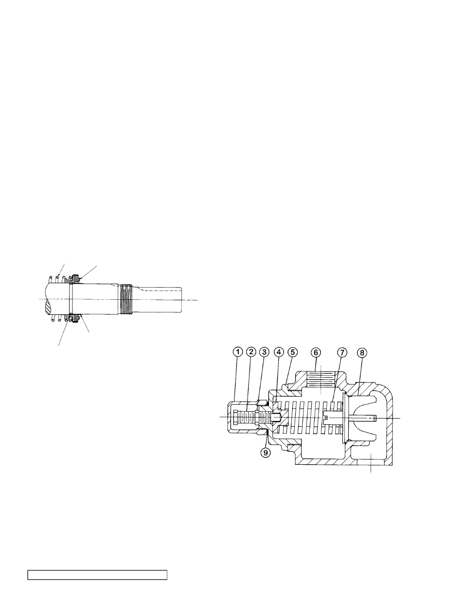
See figure 5. Coat the inside of the rotary member
and the outside of the tapered sleeve with light oil Be sure
the shaft is free of nicks and burrs Place the spring and
rotary member on the shaft, spring first, over the sleeve and
against the hub of the rotor Remove the tapered sleeve
2. Flush the sealing faces of both the rotary member and
seal seat with light oil and install rotor and shaft Push
the rotor and shaft into the casing slowly until the ends
of the rotor teeth are just beyond the face of the casing
3. Place the idler on the idler pin and the O-ring head
gasket on the head Place the head assembly on the
pump and tighten the capscrews evenly and securely
The seal is now automatically compressed to its proper
working length
4. Pack the single row ball bearing with grease and install
in the casing Install the snap ring in GG, HJ and HL
pumps
NOTE: The AS, AK and AL pumps do not have a
snap ring, but the bearing retainer washer must be
assembled over the end of the shaft before the bearing
is assembled
5. Place the bearing spacer over the shaft and against the
single row ball bearing in the casing (AS, AK, and AL
size pumps
6. Install the snap ring in the groove in the shaft on the HJ
or HL size pumps
fIgURE 5
SPRINg
MECHaNICaL SEaL
(ROTaRY MEMbER)
COaT WITH LIgHT OIL
bEfORE aSSEMbLY
TaPERED SLEEVE
fIgURE 6
“gg” , “HJ” aND “HL” SIZE