Assembly – Viking Pump TSM343.3: Vi-Corr Pumps User Manual
Page 12
SECTION TSM
343.3
ISSUE
F
PAGE 12 OF 20
3. Hold the head of the pump and gently tap on the sides of the pump bracket with a soft faced
hammer, alternating sides of the pump. This should slowly separate the sections. Note the
position of alignment sleeves for assembly. Do not hit the sections hard or use a screwdriver
to pry them apart as this may damage the mating surfaces.
NOTE: If pump has 2 casing and gear sets (RP-40724) and (RP-40732), the casing and gears
are matched sets. Keep the individual casing and gears together. Reference Figure 7.
4. After the pump is apart, inspect all parts for signs of wear. Look carefully at the shaft,
bushings, inside of casing, gear teeth, lip seals, and the faces of the pump sections that are
located on each side of the casing for signs of wear.
5. If replacing the shafts, remove the retaining rings from both sides of the gear. Press the gear
off the shaft and remove the drive pin(s) or balls from the shaft.
6. Check the bracket ball bearing for roughness. Roughness can be determined by turning the
inner race by hand. Replace if the bearing has roughness.
7. If replacing the bracket bearing or product lip seal, remove the outer snap ring holding the
bearing in place, and remove the bearing and inner bearing snap ring. Gently tap out the lip
seal with a punch and hammer, alternating sides of lip seal.
8. If replacing the mechanical seal, remove the stationary seal seat from the bracket and slide
the rotating member of the seal off the drive shaft.
9.Visually inspect the pump O-rings. If the O-rings are PTFE (appear to be white), it strongly
recommended to replace rather than reuse.
9. If pump has a relief valve, remove the acorn nut covering the relief valve adjusting screw.
Measure the distance of the relief valve adjusting screw to the pump surface and record
this length. Finish disassembling the relief valve and inspect the seat in the casing and the
poppet for signs of wear or foreign matter on either surface.
Assembly
•
The pump is ready to be reassembled after all parts have been changed and worn parts
replaced.
•
Use a suitable lubricant compatible with the fluid being handled when reassembling the
pump.
•
Make sure all holes machined in the bracket are clean and that the mating surfaces of each
section are free of any dents or burrs.
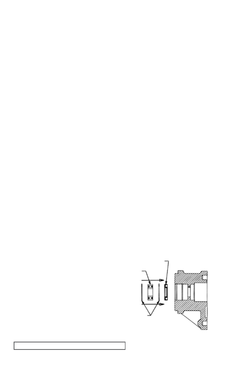
1. If installing new lip seals, press the product side (inboard) of lip seal into the bracket. See
Figure 9. Press the lip seal protecting the ball
bearing (outboard) into the bracket with lip
facing inward.
2. Pack silicone or other grease against outboard
lip seal. Install the inner internal snap ring, ball
bearing, and outer internal snap ring. Slide the
shaft into the bracket ball bearing and install
the snap ring.
3. Place the bracket, mounting face down, on
blocks to allow stable assembly of the pump.
Place O-ring into the O-ring groove. Install
alignment sleeves into the proper holes by
tapping with a soft faced hammer.
INTERNAL
SNAP RINgS
BALL
BEARINg
BEARINg
LIP SEAL
FIgURE 9