Assembly – Viking Pump TSM343.3: Vi-Corr Pumps User Manual
Page 10
SECTION TSM
343.3
ISSUE
F
PAGE 10 OF 20
7. If replacing the bracket bearing or product lip seal, remove the outer snap ring holding the
bearing in place, and remove bearing and inner bearing snap ring. Gently tap out the lip seal
with a punch and hammer, alternating sides of the lip seal.
8. Visually inspect the pump O-rings. If the O-rings are PTFE (appear to be white), it strongly
recommended to replace rather than reuse.
9. If the pump has a relief valve, remove the acorn nut covering the relief valve adjusting
screw. Measure the distance of the relief valve adjusting screw to the pump surface and
record this length. Finish disassembling the relief valve and inspect the seat in the casing
and the poppet for signs of wear or foreign matter on either surface.
Assembly
•
The pump is ready to be reassembled after all parts have been changed and worn parts
replaced.
•
Use a suitable lubricant compatible with the fluid being handled when reassembling the
pump.
•
Make sure all holes machined in the bracket are clean and that the mating surfaces of each
section are free of any dents or burrs.
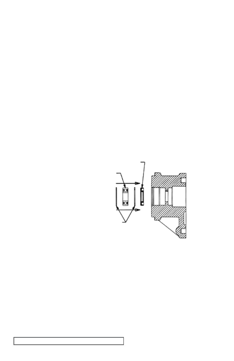
1. If installing new lip seals, press the
product side (inboard) lip seal into
the bracket. See Figure 8. Press
the lip seal protecting the ball
bearing (outboard) into the bracket
with lip facing inward.
2. Pack silicone or other grease
against the outboard lip seal.
Install the inner internal snap ring,
ball bearing, and outer internal
snap ring. Slide the shaft into
bracket ball bearing and install the
snap ring.
3. Place the bracket, mounting face
down, on blocks to allow stable
assembly of pump. Place O-ring
into the O-ring groove. Install the
alignment sleeves into the proper holes by tapping with a soft faced hammer.
4. Slide the separation plate onto the alignment sleeves with O-ring groove up and the side
notch positioned on the inlet side of the pump. Place O-ring into the O-ring groove.
RP-0724 and RP-0732 only. Lubricate the bushings in the separation plate with oil or
compatible liquid. Place the drive pin or pins in the groove on the driver shaft and slide
the gear onto the shaft over the pins. Install the driven shaft and gears into remaining the
bushing bore. The driven gear should be attached to the shaft with drive pin or pins and
snap rings. Slide the casing onto the alignment pins with O-ring groove up and lubricate
gears. Place O-ring in the O-ring groove.
NOTE: Gears and casing are matched sets and must be assembled in pump together.
FIgURE 8
BEARINg
LIP SEAL
BALL
BEARINg
INTERNAL
SNAP RINgS