Installation of carbon graphite bushings, Pressure relief valve instructions, Danger – Viking Pump TSM340.1: SG-10, SG-14 User Manual
Page 8
SECTION TSM
340.1
ISSUE
D
PAGE 8 OF 11
INSTALLATION OF CARBON
GRAPHITE BUSHINGS:
When installing carbon graphite bushings, extreme care must
be taken to prevent breaking. Carbon graphite is a brittle
material and is easily cracked. If cracked, the bushing will
quickly disintegrate. Using a lubricant and adding a chamfer
on the bushing and the mating part will help in installation.
The additional precautions listed below must be followed for
proper installation.
1. A press must be used for installation.
2. Be certain bushing is started straight.
3. Do not stop pressing operation until bushing is in proper
position. Starting and stopping will result in a cracked
bushing.
4. Check bushing for cracks after installation.
Carbon graphite bushings with extra interference fits are
frequently furnished for high temperature operation. These
bushings must be installed by a shrink fit.
1. Heat bracket for idler to 750ºF.
2. Install cool bushing with a press.
3. If facilities are not available to reach 750ºF. temperature,
it is possible to install with 450ºF. temperature; however
the lower the temperature the greater the possibility of
cracking the bushing.
Consult factory with specific questions on high temperature
applications.
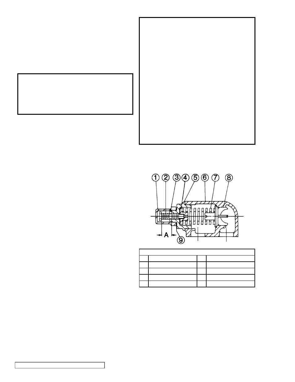
VALVE - LIST OF PARTS
1.
Valve Cap
6.
Valve Body
2.
Adjusting Screw
7.
Valve Spring
3.
Lock Nut
8.
Poppet
4.
Spring Guide
9.
Cap Gasket
5.
Bonnet
PRESSURE RELIEF VALVE
INSTRUCTIONS:
Before opening any Viking pump liquid
chamber (pumping chamber, reservoir, relief
valve adjusting cap fitting etc.) Be sure:
1. That any pressure in chamber has been
completely vented through suction or
discharge lines or other appropriate
openings or connections.
2. That the driving means (motor, turbine,
engine, etc.) has been “locked out” or made
non- operational so that it cannot be started
while work is being done on pump.
3. That you know what liquid the pump has been
handling and the precautions necessary to
safely handle the liquid. Obtain a material
safety data sheet (MSDS) for the liquid to be
sure these precautions are understood.
Failure to follow above listed precautionary
measures may result in serious injury or death.
DANGER !
FIGURE 4
11. Slide the seal holder (seal seat facing rotating face) over
the shaft and into the bracket until it contacts the rotating
face. Be careful that the o-ring does not get damaged
during installation.
12. Slide the outboard bearing over the shaft until it contacts
the seal holder.
13. Force will need to be exerted on the bearing to overcome
the seal spring force in order to install the internal snap
ring. Install the internal snap ring.
DANGER!
Before starting the pump, be sure all drive
equipment guards are in place.
Failure to properly mount guards may result in
serious injury or death.