Special information, Installation, Danger – Viking Pump TSM340.1: SG-10, SG-14 User Manual
Page 3
SECTION TSM
340.1
ISSUE
D
PAGE 3 OF 11
SPECIAL INFORMATION:
DANGER !
Before opening any Viking pump liquid cham-
ber (pumping chamber, reservoir, relief valve
adjusting cap fitting etc.) Be sure:
1. That any pressure in the chamber has
been completely vented through the suction or
discharge lines or other appropriate openings
or connections.
2. That the driving means (motor, turbine,
engine, etc.) has been “locked out” or made
non- operational so that it cannot be started
while work is being done on pump.
3. That you know what liquid the pump has
been handling and the precautions necessary
to safely handle the liquid. Obtain a material
safety data sheet (MSDS) for the liquid to be
sure these precautions are understood.
Failure to follow above listed precautionary
measures may result in serious injury or death.
INSTALLATION:
GENERAL:
The following items must be considered prior to pump
installation:
1. Location - locate the pump as close as possible to
supply of liquid being pumped. If possible locate pump
below liquid supply. Viking pumps are self-priming; but,
the better the suction conditions the better the pump will
perform.
2. Accessibility - pump must be accessible for inspection,
maintenance and repair.
3. Suction/Discharge - SG Series pumps are designed for
clockwise rotation as standard (viewed from end of shaft).
ROTATION: Viking external gear pumps can be offered in
a clockwise (-G0) or counter clockwise (-G1) rotation. The
intended rotation and inlet / outlet port positions are noted on
the pump nameplate. Do not run the pump in reverse, or the
seal will be exposed to full discharge pressure.
PRESSURE RELIEF VALVES:
1. Viking pumps are positive placement pumps and must be
provided with some sort of pressure protection. This may
be a relief valve mounted directly on the pump, an inline
pressure relief valve, a torque limiting device or a rupture
disk.
2. Relief valve adjusting screw cap must always point
towards suction side of pump.
3. Pressure relief valves cannot be used to control pump
flow or regulate discharge pressure.
For additional information on pressure relief valves, refer to
Technical Service Manual TSM000 and Engineering Service
Bulletin ESB-31.
MOUNTING:
1. Surfaces pump mounts against must be clean and flat.
2. For NEMA Mount, use SAE Grade 5 or better capscrews
to mount pump.
For IEC Mount, use Class 8.8 or better capscrews to
mount pump.
3. Standard SG Series pumps are designed to be used
with jaw type couplings that do not induce axial thrust on
the pump shaft. If an improper type of coupling is used,
internal damage may result.
4. Do not strike or press the pump drive coupling to install.
Internal pump damage will result. If the coupling does not
slide onto the shaft, inspect the coupling, shaft and key for
nicks or burrs and remove.
5. If the pump is to be belt or gear driven, the overhung load
option must be specified.
6. Once the pump has been mounted and the coupling
installed, it is recommended to put lube oil into the suction
port and turn the pump by hand to make sure it turns freely.
ALIGNMENT:
Check alignment after mounting.
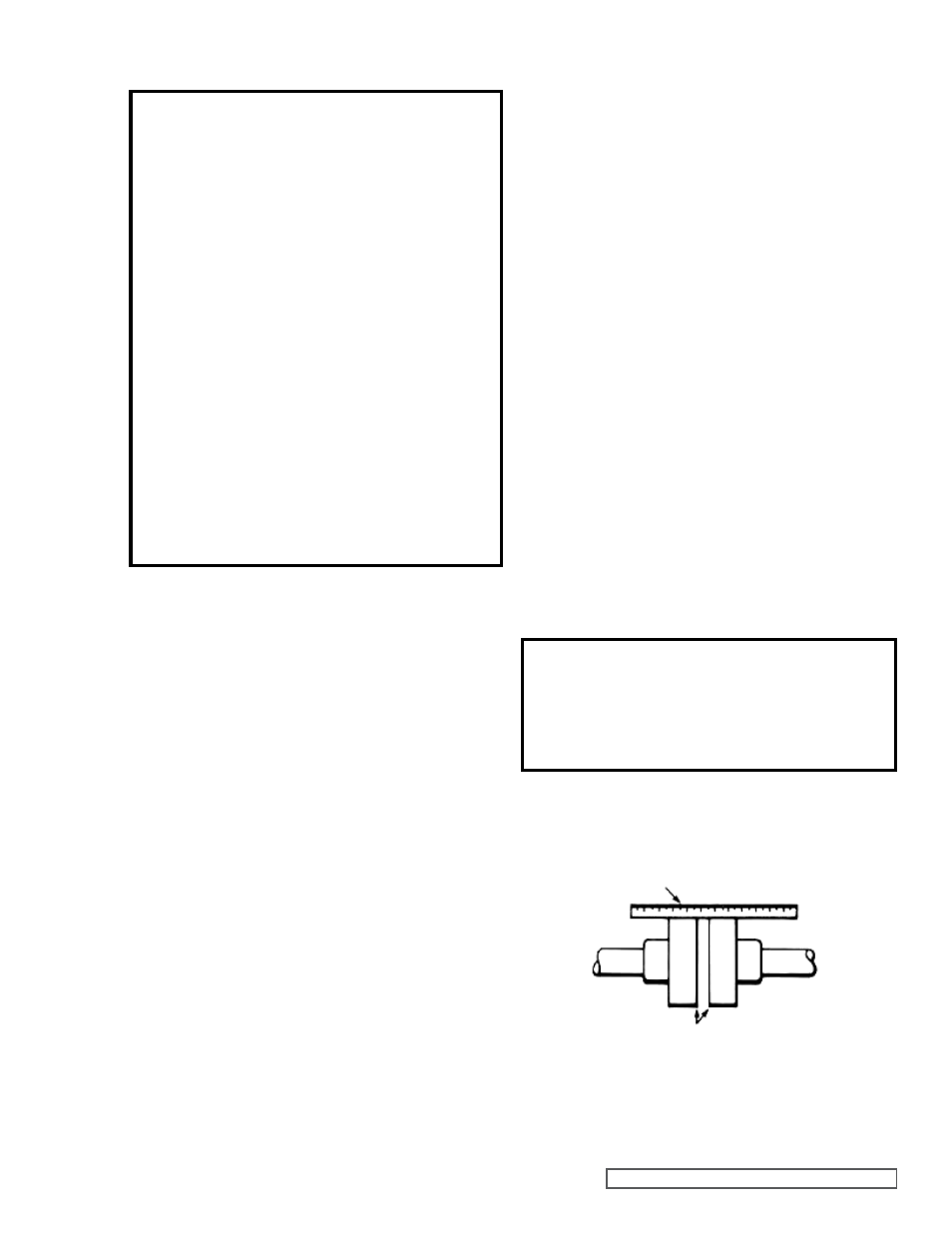
1. If unit has flexible coupling, remove any coupling guards or
covers and check alignment of coupling halves. A straight
edge (piece of key stock will work) across coupling must
rest evenly on both rims at top, bottom and sides. See
Figure 1.
2. Make final check on alignment after piping is hooked up.
DANGER!
Before starting the pump, be sure all drive
equipment guards are in place.
Failure to properly mount guards may result in
serious injury or death.
USE STRAIGHT EDGE. THESE
SURFACES MUST BE PARALLEL.
CHECK WIDTH BETWEEN THESE SURFACES WITH INSIDE
CALIPERS OR FEELER GAUGE TO BE CERTAIN THE FACES
ARE EQUAL DISTANCE APART AND PARALLEL.
FIGURE 1