Danger – Viking Pump TSM310.1: C-FH 32/432 User Manual
Page 6
SECTION TSM 310.1
ISSUE
E
PAGE 6 OF 7
Be especially careful to keep mechanical seal parts clean.
Minute dirt particles, especially on seal faces, will cause
leakage. Never touch seal faces with anything except clean
hands or a clean cloth.
NOTE: The lapped face of the carbon wear ring must face
toward the shaft end of the pump. Be sure the notches on the
edge of the carbon wear ring mate with the retainer lugs in
the rotary member.
4. When reassembling a mechanically sealed pump, place
the spring washer and spring on the shaft,
see figure 5,
Page 4. Coat the shaft and the inside of the rubber
bellows of the seal rotary member with light oil. Slide the
rotary member part way down the shaft.
Oil the lapped faces of the rotary member and the seal seat.
Slide the seal seat on the shaft until it contacts the rotary
member and then push the complete seal into the casing.
Replace the packing nut and tighten.
Your pump is now completely assembled. Once again turn
the pump shaft by hand to be sure it turns freely. Start the
pump with a supply of liquid in the suction line, since the
pump should not be run dry.
5. If the pump has packing rather than a mechanical seal,
place the spring and inner packing gland on the shaft and
slide into the pump. Next install the packing. Stagger the
joints in the packing a half turn and add lube oil between
each ring of packing. Push the outer packing gland in the
casing, and replace the packing nut and tighten.
Viking pumps are positive displacement pumps and must
be provided with some sort of pressure protection. This may
be a relief valve mounted directly on the pump, an inline
pressure relief valve, a torque limiting device or a rupture
disk. Pressure relief valves cannot be used to control pump
flow or regulate discharge pressure.
The pressure setting is increased by turning the adjusting
screw in and decreased by turning the adjusting screw out.
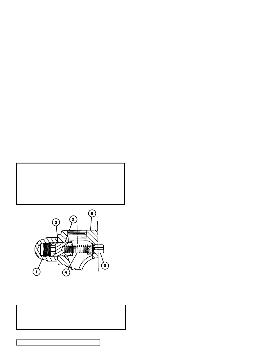
fIgURE 7
SAFETY RELIEF VALVE - C, F, FH SIZE
VaLVE - LIST Of PaRTS
1. Adjusting Screw Cap
4. Spring
2. Gasket for Cap
5. Poppet
3. Adjusting Screw
6. Casing
DaNgER !
Before starting pump, be sure all drive
equipment guards are in place.
failure to properly mount guards may
result in serious injury or death.
PRESSURE RELIEf VaLVE
INSTRUCTIONS
SPECIaL PUmP DESIgNS
Pumps furnished with a PTFE Mechanical seal require a
special rotor and shaft with drive pin installed for positive drive
of the rotating member. All other assembly and disassembly
instructions are the same.