Installing casing bushing, Assembly – Viking Pump TSM310.1: C-FH 32/432 User Manual
Page 5
SECTION TSM 310.1
ISSUE
E
PAGE 5 OF 7
The casing bushing can be replaced in the following manner:
Insert a bar approximately 0.94” diameter and at least 3.5”
long in the packing or seal end of the casing and press the
bushing out of the casing.
When installing a new carbon graphite bushing, extreme
care should be taken to prevent breakage as carbon graphite
is a brittle material and easily cracked. When cracked the
bushing may quickly disintegrate in operation. An arbor press
should always be used and the bushing should be installed in
one even uninterrupted stroke of the press. Dip the bushing
in lube oil and start the bushing in the head end of the casing.
Press until located to the “A” dimension in
figure 6.
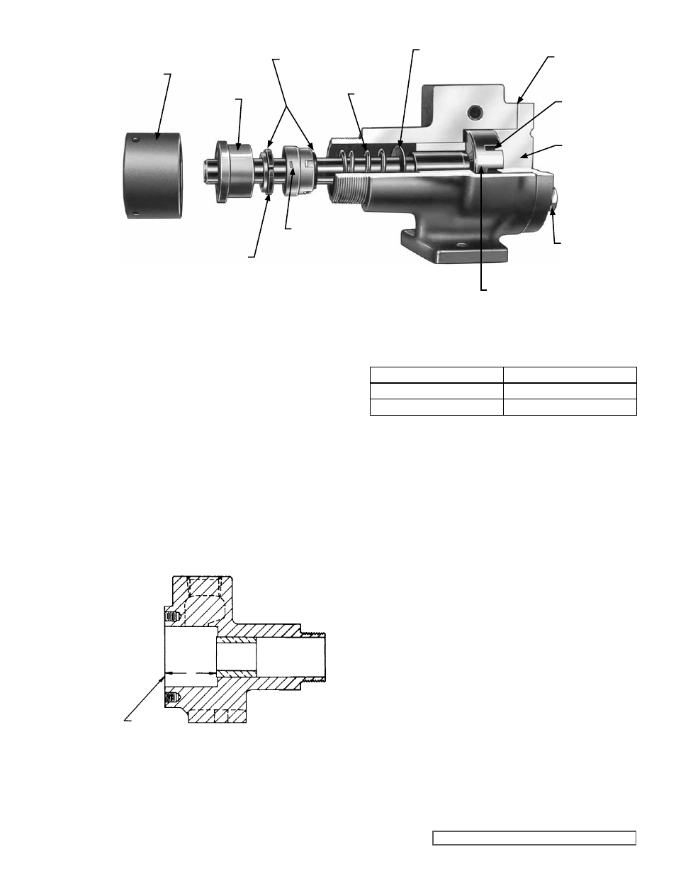
INSTaLLINg CaSINg BUSHINg
fIgURE 5
fIgURE 6
The end clearance within the pump is governed by the location
of the casing bushing as well as the number of head gaskets.
To correctly position the casing bushing in the casing, see
note in step 3 of
aSSEmBLY.
PUmP SIZE
“a” DImENSION
C
0.88” to 0.94”
F & FH
1.19” to 1.25”
1. Clean all parts thoroughly.
2. Place the rotor and shaft in the casing.
3. Put the head gaskets on the head and the idler on the
idler pin projecting from the head. Replace the head in
the casing; tighten the cap screws.
NOTE: If a new casing bushing has been installed in the
casing, use only one .002” head gasket on the head and
tighten the capscrews evenly and securely. This will correctly
position the bushing in the casing. Remove the head, add
one .002” head gasket and replace the capscrews and tighten
securely.
NOTE: Turn the shaft by hand to be certain it turns freely.
aSSEmBLY
IDLER
SPRINg
PaCKINg NUT
HEaD aND
IDLER PIN
HEaD
CaPSCREWS
CaRBON WEaR RINg
SPRINg WaSHER
HEaD gaSKETS
RETaINER LUg
ROTaRY
mEmBER
ROTOR aND SHafT
SEaL SEaT
HEaD
faCE
A