Viking Pump TSM310.1: C-FH 32/432 User Manual
Page 4
SECTION TSM 310.1
ISSUE
E
PAGE 4 OF 7
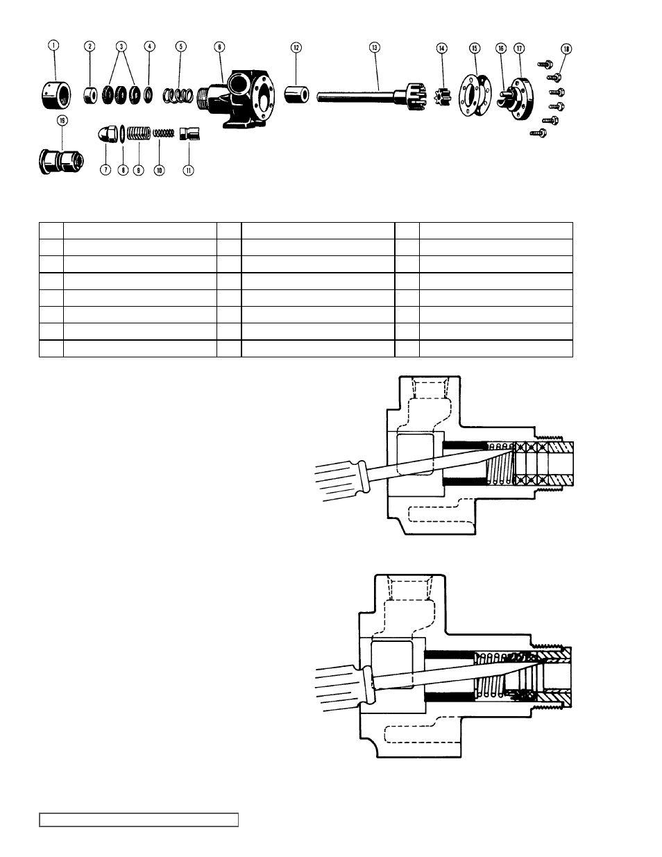
fIgURE 2
EXPLODED VIEW SERIES 32 aND 432
ITEm
NamE Of PaRT
ITEm
NamE Of PaRT
ITEm
NamE Of PaRT
1
Packing Nut
8
Gasket for Cap
15
Head Gaskets
2
Outer Packing Gland (Series 32 only)
9
Adjusting Screw
16
Idler Pin
3
Packing (Series 32 only) (3 Rings Req’d)
10
Spring
17
Head
4
Inner Packing Gland (Series 32 only)
11
Poppet
18
Capscrews
5
Packing Spring (Series 32 only)
12
Casing Bushing
19
Mechanical Seal (Series 432 only)
6
Casing
13
Rotor and Shaft Assembly
7
Adjusting Screw Cap
14
Idler
1. Remove the capscrews, the head and the idler from the
pump. It may be necessary to apply a slight pressure on
the drive end of the rotor shaft to free the head from the
casing.
DO NOT PRY the head from the casing as this
may damage and mar the gasket surfaces.
2. Remove idler from idler pin. If the idler pin is worn, both
the idler pin, and idler should be replaced.
3. Next, completely remove the rotor and shaft assembly
from the casing by exerting pressure on the drive end of
the shaft.
4. Remove the packing nut.
5. The pump is now ready for removal of the packing or
mechanical seal.
Refer to figure 3 or 4 for example. It
is recommended a new mechanical seal or packing rings
be used every time a pump is completely disassembled.
All parts should be examined for wear before the pump is put
together. When making major repairs, such as replacing a
rotor and shaft assembly, it is usually considered advisable to
also install a new casing bushing.
fIgURE 3
fIgURE 4
mECHaNICaL
SEaL (432)
PaCKED
(32)