Assembly – Viking Pump TSM212: H-LL 724/4724 User Manual
Page 6
SECTION TSM 212
ISSUE
F
PAGE 6 OF 9
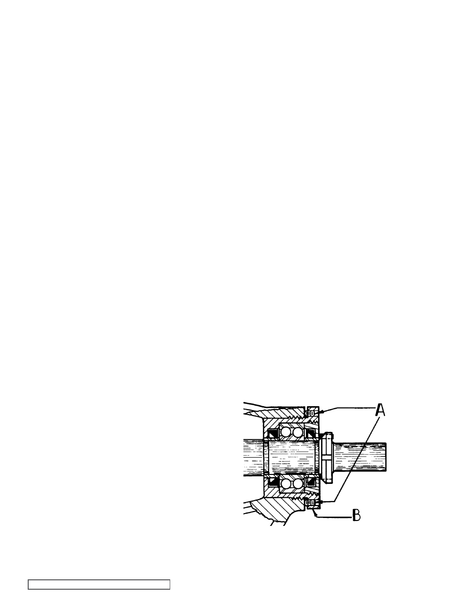
fIgURE 5
6. Loosen the radial set screws in the bearing housing
flange that locks the end cap in place and using a spanner
wrench, remove the end cap, lipseal and bearing spacer
collar.
7. Remove the 2-row ball bearing and inner spacer collar
from bearing housing, wash and inspect bearing for wear
or damage and replace, if necessary.
8. Loosen two axial set screws in bearing housing flange
and remove housing from bracket. Examine lipseals in
end cap and bearing housing and replace with lips facing
as shown in
figure 5 if not in first class condition.
9. On 4724 series pumps, inspect the lipseal in the casing
and replace if necessary. This lipseal must be removed
if replacement of the casing bushing is necessary. See
Step 12.
10. If it is deemed necessary to replace bracket bushing
and/or repack series 724 pumps, remove packing gland
nuts, old packing and lantern ring and packing retainer
washer. See Step 12.
11. Examine casing for excessive wear and replace if
necessary.
12. The casing bushing should be inspected for wear
and replaced if necessary. See Steps 9 and 10. If it is
necessary to install a new carbon graphite bushing,
extreme care should be taken to prevent breaking, as it
is a brittle material and easily cracked. If cracked these
bushings will quickly disintegrate. An arbor press should
always be used in installing carbon graphite bushings.
Be sure the bushing is started straight.
CAUTION: DO
NOT STOP the pressing operation until the bushing is
in proper position. Starting and stopping this operation
may result in a bushing crack. Check bushings for
cracks after installation. Carbon graphite bushings with
extra interference fits are frequently furnished for high
temperature operation. Consult Factory. For additional
information on high temperature applications, see
Engineering Service Bulletin ESB-3.
13. Mechanical Seal (Series 4724): If the mechanical seal
in your pump ever fails, it can be easily replaced with a
new seal. There are two basic parts to this seal. They
are the rotary member and stationary seat
(See figure
4). Loosen the set screws holding the rotary member on
the shaft. Remove the rotary member from the shaft and
the stationary seal seat from the casing. The principle
of the mechanical seal is the contact between the rotary
and stationary members. These parts are lapped to a
high finish and their sealing effectiveness depends upon
complete contact.
1. Installing new seal (Series 4724): The seal is simple to
install and good performance will result if care is taken
during installation.
(See figure 4) for parts identification.
NOTE: Never touch the sealing faces with anything
except the fingers or a clean cloth. Clean the rotor hub
and casing seal housing, making sure both are free from
dirt and grit. Coat the outside diameter of the seal seat
and the inside diameter of the seal housing bore with
light oil. Start the seal seat in the seal counterbore. Be
sure the seat anchor pins are aligned so as to engage
the slots in the end of the casing bushing as in
figure 6.
Using a cardboard cushion to protect the lapped face of
the seal seat, tap the seat assembly to the bottom of the
seal counterbore with a wooden ram and a light hammer.
(Factory installation is accomplished with a special
arbor. It has a major diameter which covers the entire
seat face and has an extension through the seat which
pilots in the casing bushing). Place the tapered sleeve
(furnished with replacement seals, H-LL sizes) on shaft
as in
figure 7. Coat the inside of the rotary member and
the outside of the tapered sleeve with the light oil. Place
rotary member on the shaft, over the sleeve and against
the hub of the rotor.
(See figure 8).
Remove the Tapered sleeve. Tighten the setscrew(s) in
the rotary member. Some seals may be equipped with
installation clips. These must be removed after seal is
placed on the proper diameter portion of the shaft.
Flush the sealing faces of both the rotary member and
stationary member with oil just before installing rotor and
shaft.
ASSEMBLY