Thrust bearing adjustment – Viking Pump TSM154: GG-AL 493/4193 User Manual
Page 8
SECTION TSM 154
ISSUE
D
PAGE 8 OF 10
Loosen two screws in face of thrust bearing assembly.
If shaft cannot be rotated freely, turn thrust bearing assembly
counterclockwise until shaft can be turned easily.
To set end clearance:
1. While turning rotor and shaft assembly, rotate thrust
bearing assembly clockwise until noticeable drag occurs.
This is zero end clearance.
2. Mark position of bearing housing with respect to the
casing.
3. Rotate thrust bearing assembly counterclockwise the
distance listed below as measured on outside of bearing
housing.
4. Tighten two setscrews in face of bearing housing after
adjustment is made to secure thrust bearing assembly
position.
For viscosities above 2500 SSU, add additional end
clearance (0.005” for GG, HJ and HL size pumps and
0.007” for AS, AK and AL size pumps).
When installing carbon graphite bushings, extreme care
must be taken to prevent breaking. Carbon graphite is a
brittle material and easily cracked. If cracked, the bushing will
quickly disintegrate. Using a lubricant and adding a chamfer
on the bushing and the mating part will help in installation.
The additional precautions listed below must be followed for
proper installation:
1. A press must be used for installation.
2. Be certain bushing is started straight.
3. Do not stop pressing operation until bushing is in proper
position, starting and stopping may result in a cracked
bushing.
4. Check bushing for cracks after installation.
THRUST bEARINg ADJUSTMENT
See figures 9 and 10.
PUMP
SIZE
DISTANCE IN INCHES
ON O.D. Of bEARINg
HOUSINg
END
CLEARANCE
GG
7/16”
0.003”
HJ, HL
9/16”
0.003”
AS, AK, AL
1/2”
0.003”
INSTALLATION Of CARbON
gRAPHITE bUSHINgS
PRESSURE RELIEf VALVE
INSTRUCTIONS
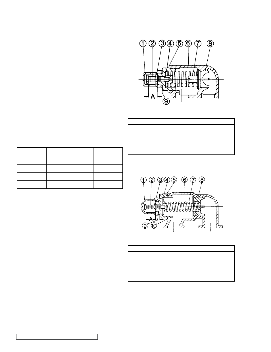
fIgURE 13
VALVE - LIST Of PARTS
1. Cap
6. Valve Body
2. Adjusting Screw
7. Spring
3. Lock Nut
8. Poppet
4. Spring Guide
9. Cap Gasket
5. Bonnet
VALVE - LIST Of PARTS
1. Cap
6. Valve Body
2. Adjusting Screw
7. Spring
3. Lock Nut
8. Poppet
4. Spring Guide
9. Cap
5. Bonnet
10. Bonnet
VALVE - gg, HJ and HL SIZES
VALVE - AS, AK and AL SIZES
fIgURE 14