Disassembly – Viking Pump TSM154: GG-AL 493/4193 User Manual
Page 4
SECTION TSM 154
ISSUE
D
PAGE 4 OF 10
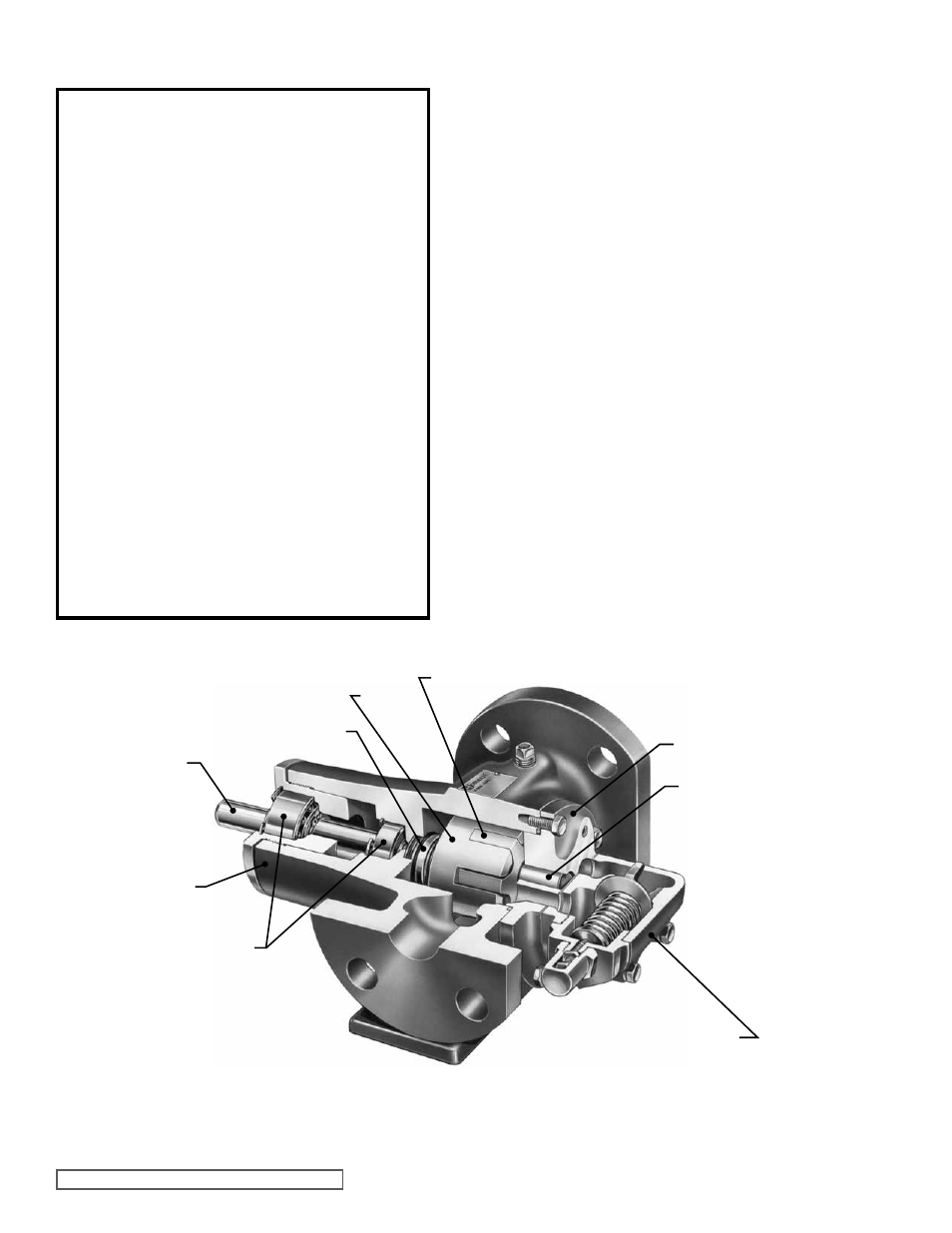
fIgURE 6
CUTAWAY fOR MODELS gg, HJ AND HL4193
CASINg
DISASSEMbLY
DANgER !
before opening any Viking pump liquid
chamber (pumping chamber, reservoir,
relief valve adjusting cap fitting, etc.)
be sure:
1. That any pressure in the chamber has
been completely vented through the
suction or discharge lines or other
appropriate openings or connections.
2. That the driving means (motor,
turbine, engine, etc.) has been “locked
out” or made non-operational so that
it cannot be started while work is
being done on pump.
3. That you know what liquid the
pump has been handling and the
precautions necessary to safely
handle the liquid. Obtain a material
safety data sheet (MSDS) for the
liquid to be sure these precautions
are understood.
failure to follow above listed
precautionary measures may result in
serious injury or death.
1. Refer to figures 7 & 8 on page 4 for model to be
disassembled and name of parts. Models 4193 & 493 are
disassembled and assembled the same. The difference
between these models is the casings.
2. Mark
the head and casing before disassembly to ensure
proper reassembly.
3. NOTE: The four valve capscrews, valve and gasket
must be removed from the GG 4193-493 model before
the six head capscrews are removed.
Remove the head capscrews.
4. Remove the head from the pump. Do not allow the idler
to fall from the idler pin. Tilt the top of the head back
when removing to prevent this. Avoid damaging the
head gasket.
5. Remove the idler and bushing assembly. If the the idler
bushing needs replacing,
see “Installation of Carbon
graphite bushings”, page 7.
6. Remove the locknut from the shaft. See figure 9 or 10.
A brass bar or piece of hardwood inserted in the port
opening and between the rotor teeth will keep the shaft
from turning.
7. Loosen the two setscrews in the face of the bearing
housing and turn the thrust bearing assembly
counterwise and remove from the casing.
See figure
9 or 10.
8. Remove
the snap ring from the shaft for GG, HJ and HL
size pumps.
See figure 9.
9. Remove
the bearing spacer from the shaft for AS, AK
and AL size pumps. See Figure 10.
10. Remove the brass bar or piece of hardwood from the
port opening.
ROTOR
IDLER
HEAD
CASINg
SHAfT
IDLER PIN
RELIEf VALVE
MECHANICAL SEAL
bALL bEARINgS