Danger – Viking Pump TSM154: GG-AL 493/4193 User Manual
Page 7
SECTION TSM 154
ISSUE
D
PAGE 7 OF 10
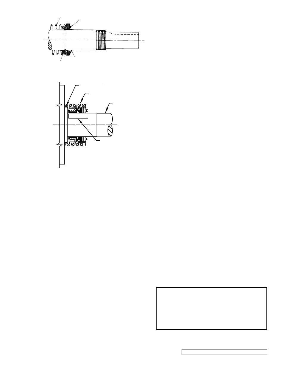
4. Place tapered installation sleeve on shaft, refer to
figure 11. Sleeve is furnished with GG, AS, AK and AL
size replacement mechanical seals. Coat rotor and shaft
assembly, tapered installation sleeve and inner diameter
of mechanical seal rotary member with a generous
amount of non-detergent SAE 30 weight oil. Petrolatum
may be used but grease is not recommended.
5. Place seal spring on shaft against rotor hub. Refer to
figure 12.
6. Slide rotary member, lapped contact surface facing away
from spring, over installation sleeve on shaft until it is
against the spring.
7. Do not compress the spring.
8. Coat the rotor and shaft assembly with non-detergent
SAE 30 weight oil. Taking care not to damage the seal
seat, start end of shaft in bracket bushing and turn from
right to left, slowly pushing until the ends of the rotor
teeth are just below the face of the casing.
9. Leave the rotor in this position. Withdrawal of rotor and
shaft may displace the carbon seal rotating face and
result in damage to the seal.
10. Place O-ring gasket on head and install head and idler
assembly on pump. Pump head and casing were marked
before disassembly to ensure proper reassembly. If
not, be sure idler pin, which is offset in pump head,
is positioned toward or equal distance between port
connections to allow for proper flow of liquid through
pump.
DANgER !
before starting pump, be sure all drive
equipment guards are in place.
failure to properly mount guards may
result in serious injury or death.
fIgURE 11
SPRINg
MECHANICAL SEAL
(ROTARY MEMbER)
TAPERED SLEEVE
COAT WITH LIgHT OIL bEfORE ASSEMbLY
MECHANICAL SEAL
(ROTARY MEMbER)
SPRINg
ROTOR HUb
SHAfT
fIgURE 12
11. Tighten head capscrews evenly.
12. If pump was equipped with a relief valve and was
removed during disassembly, install with new o-rings or
gaskets. Relief valve adjusting screw cap must always
point towards suction port.
Refer to figure 5, page 2.
For relief valve repair or adjustments,
see PRESSURE
RELIEf VALVE INSTRUCTIONS, Page 7.
13. In 2005, the use of single seal bearings were phased
out. Pumps now use “Sealed for Life” bearings that
have seals on both sides. The new bearings can be
installed either side first and do not need to be packed
with grease. For older models with single seal bearings,
pack the inner ball bearing with multi-purpose grease,
NLGI #2
NOTE: AS, AK and AL size pumps do not have a snap
ring, a bearing retainer washer must be assembled over
end of shaft before the bearing is assembled.
See figure
10.
14. Place bearing spacer over shaft and against single row
ball bearing in casing (AS, AK and AL size pumps).
See
figure 10.
Install snap shaft ring in groove in the shaft (GG, HJ and
HL size pump.
See figure 8.
15. Pack lubrication chamber between inner ball bearing and
double row ball bearing in the thrust bearing assembly
approximately half full with multi-purpose grease,
NLGI#2.
See figures 9 and 10.
16. Pack double row ball bearing with multi-purpose grease,
NLGI#2 and press into bearing housing with shield side
toward coupling end of shaft.
See figure 9. (AS, AK and
AL size pumps do not use a shielded bearing). Install
snap ring to hold bearing in place on GG, HJ and HL size
pumps.
NOTE: On AS, AK and AL size pumps, install lip seal in
bearing house end cap. The lip should face towards end
of shaft. Put bearing spacer sleeve in lip seal and install
in bearing housing and tighten setscrews securely.
See
figure 20.
17. Insert a piece of brass or hard wood through port opening
between rotor teeth to keep shaft from turning.
18. Start thrust bearing assembly into casing. Turn by hand
until tight. This forces rotor against head. Replace and
tighten locknut on shaft.
19. Remove brass piece or hardwood from port opening.
Adjust pump end clearance,
refer to page 7.