Disassembly, Danger – Viking Pump TSM142.2: LS-M 225/4225 User Manual
Page 9
SECTION TSM 142.2
ISSUE
E
PAGE 9 OF 14
DISaSSEMBlY
DaNgER !
Before opening any Viking pump liquid
chamber (pumping chamber, reservoir,
relief valve adjusting cap fitting, etc.)
Be sure:
1. That any pressure in the chamber has
been completely vented through the
suction or discharge lines or other
appropriate openings or connections.
2. That the driving means (motor,
turbine, engine, etc.) has been “locked
out” or made non-operational so that
it cannot be started while work is
being done on pump.
3. That you know what liquid the
pump has been handling and the
precautions necessary to safely
handle the liquid. Obtain a material
safety data sheet (MSDS) for the
liquid to be sure these precautions
are understood.
Failure to follow above listed
precautionary measures may result in
serious injury or death.
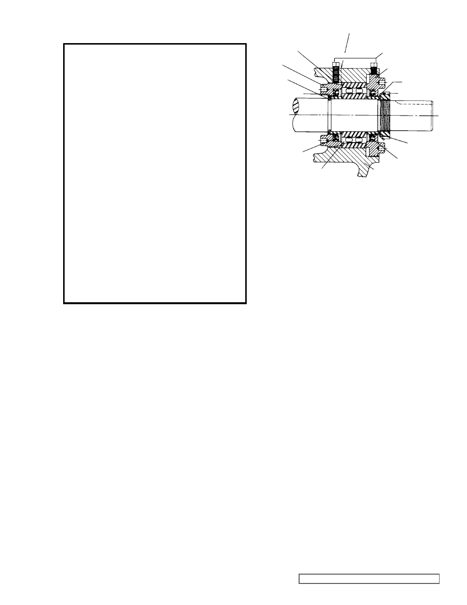
gREaSE FITTINg
SETSCREWS
OUTER END CaP
lOCKWaSHER
lOCKNUT
OUTER
SPaCER
COllaR
OUTER lIP
SEal
BRaCKET
Ball BEaRINg
INNER
lIP SEal
INNER SPaCER
COllaR
HalF
ROUND
RINgS
INNER
END CaP
NYlON INSERT
FIgURE 5
1. Mark head and casing before disassembly to make sure
they are reassembled properly. Remove the head from
the pump.
CaUTION: DO NOT allOW THE IDlER TO Fall
FROM THE IDlER PIN.
Tilting the top of the head back as it is removed will
prevent the idler from falling. Avoid damaging the head
gasket if possible. If pump is furnished with a relief valve
it need not be removed from the head or disassembled
at this point
(see page 13 for “Pressure Relief Valve
Instructions”). If the pump has a jacket head plate,
this plate will separate from the head when the head
is removed. The gasket for jacket head plate between
the head and the jacket head plate should be removed
and the gasket surfaces on the above parts cleaned.
Disassembly will probably require replacement of the
gasket for jacket head plate between the pump head and
jacket head plate. These gaskets should be carried as
spare parts for pumps thus equipped.
2. Remove the idler and bushing assembly.
3. Bend up tang of lockwasher and with a spanner wrench
remove the locknut and lockwasher from the shaft.
NOTE: A piece of hard wood or brass inserted in the
casing port and between the rotor teeth will prevent the
shaft from turning.
4. STaNDaRD MECHaNICal SEal (Type 9, PTFE is
standard). If the mechanical seal fails it can be replaced
with a new one. There are two basic parts to the
mechanical seal, the rotary member and the stationary
seat.
See Figure 8, page 11. To remove the mechanical
seal loosen the setscrews around the outside of the
mechanical seal which lock it to the shaft. Access to the
seal setscrews is through the seal access hole located on
the left hand side of the pump mounting bracket (viewed
from the shaft end).
See Figure 8, page 11. Rotate the
rotor shaft so all setscrews come into view (three on Q,
QS & M, four on LS). Remove the nuts holding the seal
holder plate. Remove the seal holder and plate.
OPTIONal MECHaNICal SEal (Type 1 or equivalent
single synthetic rubber bellows style). It uses a set
collar behind the seal spring.
See Figure 7, page 11.
Two setscrews must be loosened before shaft can be
removed. Access to the collar setscrews is through the
seal access hole on the right hand side of the mounting
bracket (viewed from the shaft end).
5. Tap the shaft toward head approximately ½ inch and
check for a pair of half circle, round wire rings, under
the inner bearing spacer collar.
NOTE: These half rings
must be removed before the rotor and shaft can be
removed from the pump (these rings are not used in the
Q, QS and M size pumps).
6. Carefully remove the rotor and shaft. As the shaft is
being removed decreasing shaft diameters tend to allow
the shaft to drop onto the bracket bushing. To avoid
damaging the bracket bushing, support the rotor and do
not allow either end of the shaft to tilt downward.
NOTE:
Considerable force may be required to remove the rotor
and shaft from the pump. Be careful seal parts are not
damaged as the rotor and shaft is removed.
7. The seal seat and rotary member of the seal can now be
removed from the side opening of bracket.