Assembly – Viking Pump TSM142.2: LS-M 225/4225 User Manual
Page 10
SECTION TSM 142.2
ISSUE
E
PAGE 10 OF 14
aSSEMBlY
8. Loosen the four setscrews over the outer and inner end
caps. Remove both end caps, ball bearing and bearing
spacer collars.
See Figure 5, page 9. NOTE: The inner
end cap can be removed through the side openings in
the bracket.
9. Clean all parts thoroughly and examine for wear or
damage. Check lip seals, ball bearing, bushings, and
mechanical seal and replace as necessary. Check all
other parts for nicks, burrs, excessive wear and replace
if necessary.
NOTE: Be sure shaft is free from burrs
and foreign particles that might damage the bracket
bushing. Scratches on the shaft in the seal area will
provide leakage paths under the mechanical seal.
10. Check casing for wear or damage while mounted to the
bracket.
1. Install the bracket bushing (if carbon graphite, see
“Installation of Carbon graphite Bushings” on page
12).
2. Assemble the rotor and shaft in the bracket. Start the
end of the shaft in the bracket bushing and turn from
right to left slowly, pushing the rotor into the casing.
3. Coat the idler pin, in the head, with light oil and place the
idler and bushing on the idler pin. If replacing a carbon
graphite idler bushing
see “Installation of Carbon
graphite Bushings” on page 12.
4. Put the head gasket on the head and install the head
and idler assembly on the pump. Tighten the head
capscrews or nuts.
5. STANDARD MECHANICAL SEAL (PTFE - see Figure
8). The seal is simple to install and good performance
will result if care is taken during installation.
NOTE: Never touch the sealing faces with anything but
the fingers of a clean cloth.
Clean the rotor shaft and bracket seal housing bore.
Make sure they are free of dirt, grit and scratches. Gently
radius the leading edge of the shaft diameter over which
the seal must be placed. A tapered sleeve is available,
at extra cost, for the “Q, QS and M” pumps from Viking
Pump Division for installation of the mechanical seal on
the shaft as in
Figure 6. The “LS” pump shaft is tapered
and an installation sleeve is not available.
Coat the tapered sleeve and the inside of the rotary
member with a generous quantity of SAE 30 non-
detergent oil. Grease is not recommended. Start
the rotary member on the shaft and over the tapered
sleeve.
CaUTION: Some seals may be equipped with installation
clips. These must be removed after seal is placed on the
proper diameter portion of the shaft.
Move the rotary member so the setscrews are directly
below the seal access holes on the left side of the bracket
(viewed from the shaft end) -
see Figure 8. Tighten all
setscrews securely to the shaft. Flush the sealing faces
of both the rotary member and seal seat with oil and
install the seal seat and a seat gasket over the end of
the shaft against the machined bracket face. Assemble
the other seal seat gasket, seal holder, seal holder plate,
capscrews and nuts and tighten securely. Remove the
tapered installation sleeve.
OPTIONal MECHaNICal SEal (See Figure 7)
Install the seal set collar - examine the set collar to be
sure that there are no burrs or scratches and that the
setscrews are withdrawn so that the shaft will
Not be scratched when the set collar is installed. Place
the set collar onto the shaft, push it into the seal chamber
until the centerline of the setscrews coincides with the
centerline of the tapped seal access holes on the right
side of the bracket (viewed from the shaft end). Tighten
all the setscrews in the set collar securely.
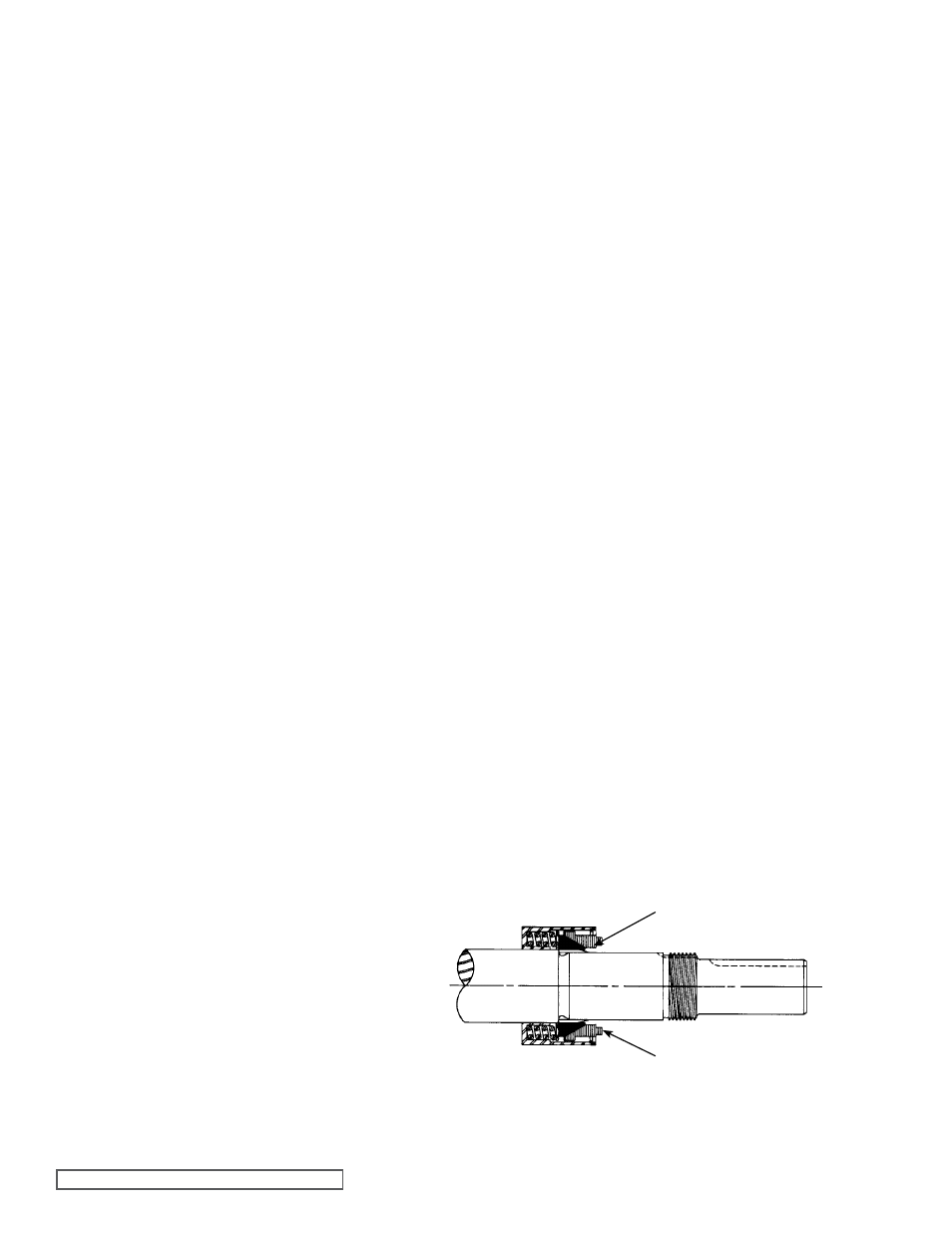
Install the rotating member of the seal - Slide the spring
over the shaft into the seal chamber and onto the set
collar pilot. Center the spring adapter (on Q, QS & M
models only) against the back of the metal retainer so
that the spring will push against the adapter and not
work itself over the back of the mechanical seal. Place
the tapered sleeve on the shaft as in
Figure 9. Apply a
liberal coating of SAE-30 lube oil to the large diameter
portion of the rotor shaft, tapered sleeve and to the inside
diameter of the mechanical seal rubber parts. Start the
rotary member of seal with its carbon face out onto the
rotor shaft and push it along the shaft until the spring is
centered against the adapter.
Install the Stationary Seal Seat - Lubricate the outside
diameter of the mechanical seal O-Ring seat gasket and
flush the lapped face with lube oil. Press the stationary
seat into the bore until the back, unlapped face, is just
inside the bore. Position the stationary seat by installing
the seal holder and secure the seal holder to the
machined face of the bracket with the seal holder plate.
Tighten the nuts securing the seal holder plate evenly so
that the seal holder will not be distorted.
Remove the tapered installation sleeve.
COaT SHaFT aND TaPERED SlEEVE
WITH lIgHT OIl BEFORE aSSEMBlY
TaPERED SlEEVE
MECHaNICal SEal
(ROTaRY MEMBER)
FIgURE 6