Danger – Viking Pump TSM142.2: LS-M 225/4225 User Manual
Page 11
SECTION TSM 142.2
ISSUE
E
PAGE 11 OF 14
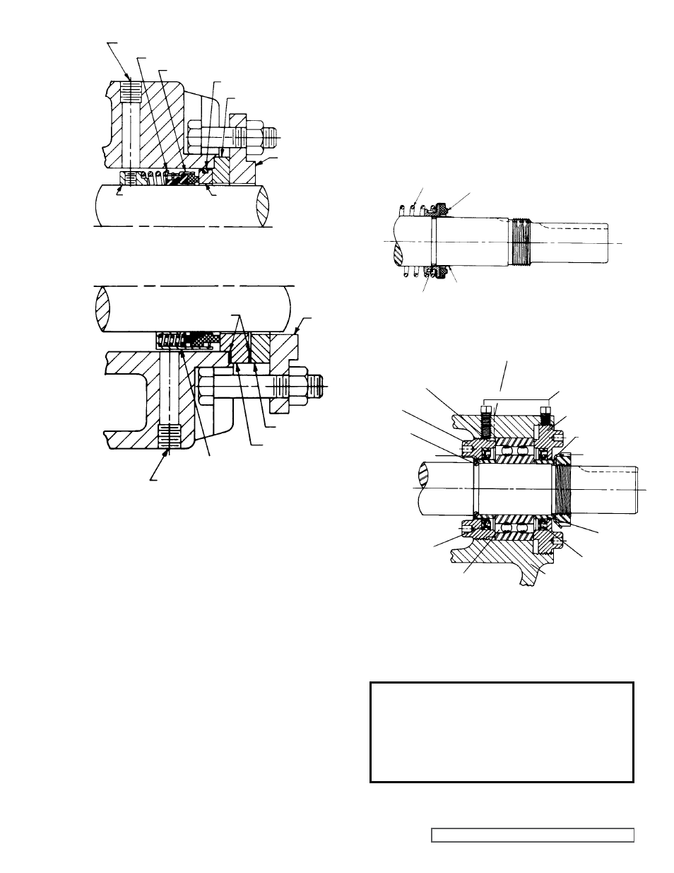
SPRINg
MECHaNICal SEal
(ROTaRY MEMBER)
TaPERED SlEEVE
COaT WITH lIgHT OIl BEFORE aSSEMBlY
gREaSE FITTINg
SETSCREWS
OUTER END CaP
lOCKWaSHER
lOCKNUT
OUTER
SPaCER
COllaR
OUTER lIP
SEal
BRaCKET
Ball BEaRINg
INNER
lIP SEal
INNER SPaCER
COllaR
HalF
ROUND
RINgS
INNER
END CaP
NYlON INSET
FIgURE 10
FIgURE 7 - OPTIONal MECHaNICal SEal
SPRINg aDaPTER
SEal aCCESS HOlE (FOR SETSCREWS)
SEal SEaT gaSKET
SEal HOlDER
SET COllaR
SEal
SEaT
MECHaNICal SEal (ROTaRY MEMBER)
SEal
HOlDER
PlaTE
RIgHT SIDE
OF PUMP
FIgURE 9
lEFT SIDE
OF PUMP
SEal aCCESS HOlE (FOR SETSCREWS)
MECHaNICal SEal (ROTaRY MEMBER)
SEal SEaT
SEal HOlDER
SEal SEaT gaSKET
SEal
HOlDER
PlaTE
FIgURE 8 - STNaDaRD MECHaNICal SEal
10. Put lockwasher and locknut on shaft. Insert length of
hardwood or brass through port opening between rotor
teeth to keep shaft from turning. Tighten locknut to 120-
150 ft.– lbs. Torque (LS) or 170-190 ft. – lbs. Torque (Q,
QS, M). Bend one tang of lockwasher into slot of locknut.
If tang does not line up with slot, tighten locknut until it
does. Failure to tighten locknut or engage lockwasher
tang could result in early bearing failure and cause
damage to rest of pump. Remove length of hardwood or
brass from port opening.
6. Slide the inner bearing spacer collar over the shaft with
recessed end toward rotor.
NOTE: The pair of half round
rings must be inserted in the groove in the shaft and then
slide the spacer collar over them.
See Figure 10 (not
used on Q and M size pumps).
7. Press the lip seal (lip toward end of shaft) into the inner
end cap and insert the end cap through the shaft end of
the bracket. With two fingers turn it clockwise (looking at
end of shaft) until it engages the threads. The bosses on
the end cap must be toward the rotor. Turn the end cap
until it projects slightly into the opening on the side of the
bracket.
NOTE: The end cap must not be turned so far
that the lip of the lip seal drops off the end of the spacer
collar on the shaft or the end cap becomes disengaged
with the threads.
See Figure 10.
8. Pack the ball bearing with multi-purpose grease, place
on the shaft and push or gently drive into place in the
bracket.
9. Install the lip seal (lip toward end of shaft) and bearing
spacer in the outer end cap and turn the end cap into the
bracket until tight against the bearing.
See Figure 10.
DaNgER !
Before starting pump, be sure all drive
equipment guards are in place.
Failure to properly mount guards may
result in serious injury or death.
11. Adjust the pump end clearance as in “Thrust Bearing
adjustment” (see Page 11).