Setting the serial port configuration switch, Usb option, Serial communication protocol – VICI EUT Universal Electric Actuator User Manual
Page 13
9
Optional Serial Interface
Setting the Serial Port Configuration Switch
Models with product numbers ending in “A” have been factory-set for RS-232; those end-
ing in “F” were set for RS-485. An “A” model can be changed to an “F” model, or vice versa,
by resetting the serial port configuration switch.
Note when switching from RS-232 to RS-485:
As discussed in the “Using the Device ID Feature” on page 7, all RS-485 communications
require an ID. If the actuator has had an ID set previously, that ID will be recalled and
retained. Otherwise, the ID will be set to the factory default value of “Z”.
To reset the switch:
1. Remove the 4 screws from the front (valve side) of the
actuator.
2. Carefully slide the assembly out of the enclosure. We
recommend that the enclosure be opened in a static-
free environment following all proper ESD protection
techniques.
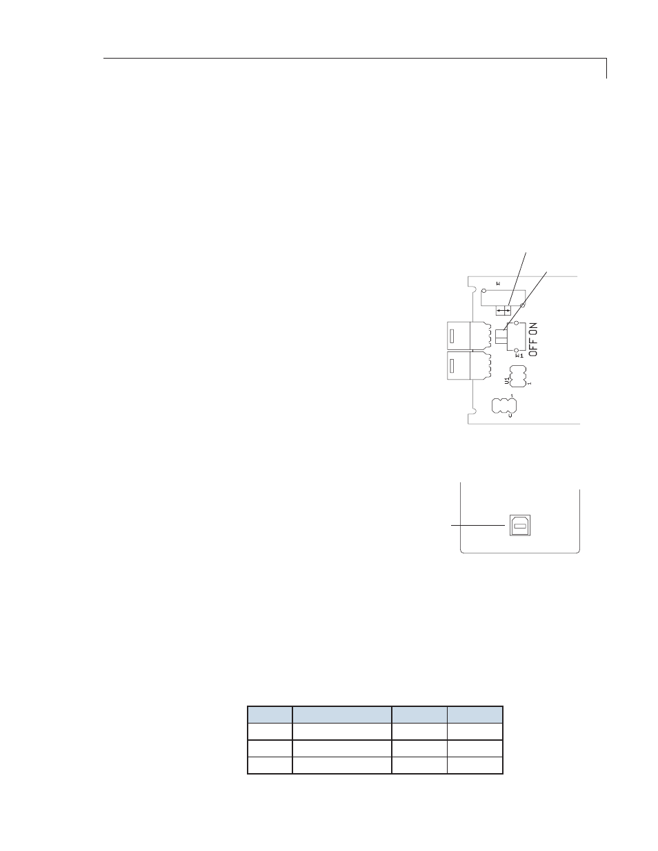
3. Locate the slide switch marked “232 <– –> 485”, and set
it to the desired position.
Note: The switch labeled “Termination On <– –> Off” is
typically left in the Off position. Unless the wiring from
the host control to the device is very long and it is the last
device at the end of a signal chain of devices, it is recom-
mended that this switch is left in the Off position.
USB Option
The USB interface installs as a virtual COM port
(VCP). The VCP driver causes the universal actua-
tor to appear as an additional COM port available
to the PC, so application software can access the
actuator in the same way it accesses a standard
COM port. Refer to “Appendix A: Installing USB
Drivers”, on page 21.
Serial Communication Protocol
Serial communication is based on an ASCII string protocol. Carriage Return (OD hex) and
Line Feed (OA hex) characters parse the communications by defining the end of each
command. A three-pin connector is used for the serial interface: pin assignments are
indicated below. Software flow control (Xon/Xoff) and hardware handshaking are not
supported. The table on the next page describes and explains all the commands available.
A fuller explanation follows.
Pin #
RS-232
RS-485
DB9*
1
Ground
Ground
5
2
Transmit to host
B (+)
2
3
Receive from host
A (-)
3
*For VICI cable I-22697
J5
J6
S 2
S
S 2
S
6
6
232
485
SeRiAl poRT
confiGuRATion SwiTch
TeRminATion
SwiTch
Figure 9: Serial port
configuration switch
USB
USB
CONNECTION
Figure 10: USB connector
on rear panel