Connections – VICI M Series User Manual
Page 9
5
BLACK
RED
WHITE
GREEN
+24
GND
GR
OUP 20 I/O
COMMUNICA
TIONS
MICRO
1
RS-232 CABLE
I-24185
Amphenol
MICROLYNX CONTROLLER
CP-CM1-P
TO
COMPUTER
1
GND
+V
PHASE B
PHASE B
PHASE A
PHASE A
POWER
SUPPLY
3
MOTOR POWER CABLE
I-23688-CE
TO
PUMP
LINE CORD
(IEC-320)
I-W-17600
TO 110
OR
220 VAC
POWER SUPPLY
PS24VDC-CE or
PS24VDC-CE-220
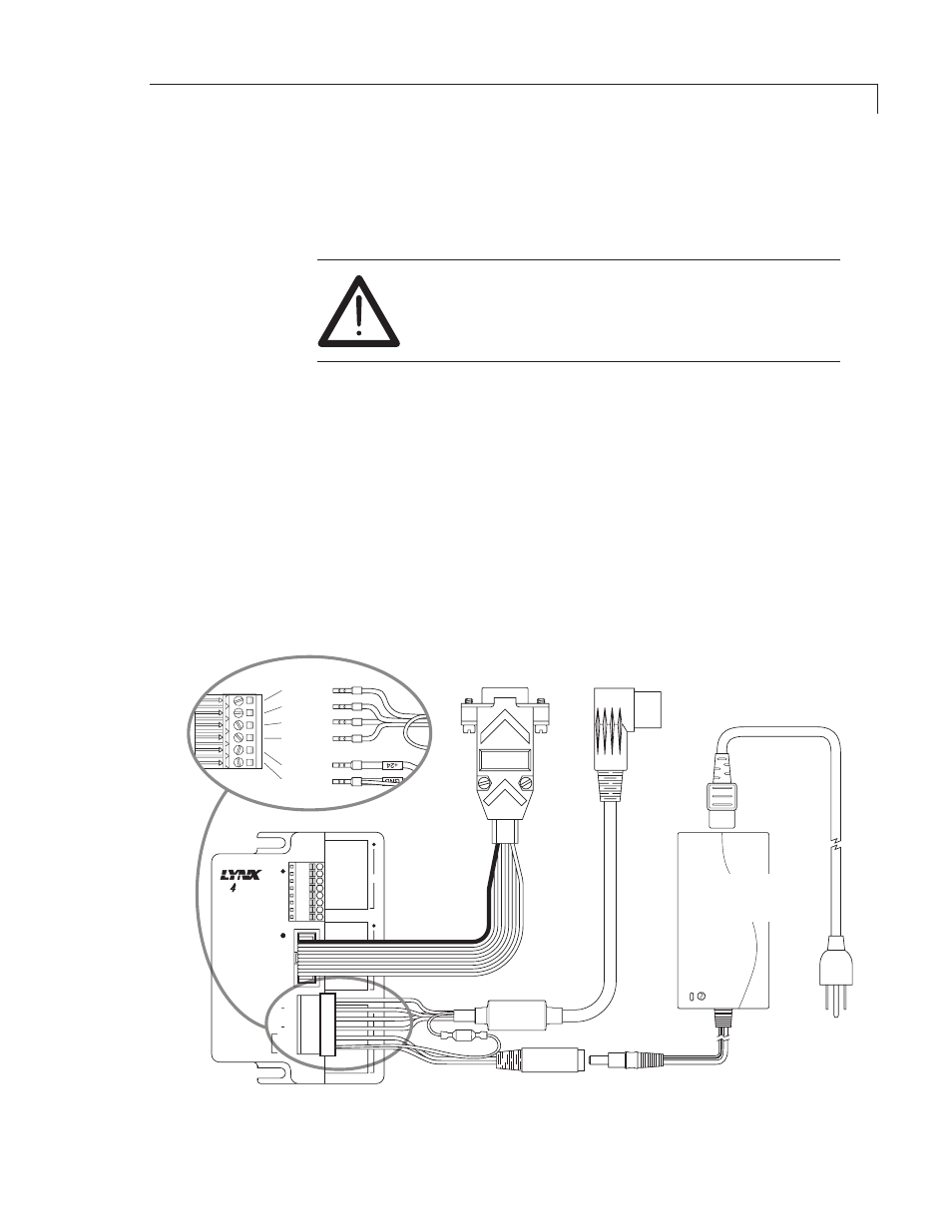
Connections
CAUTION: Supply power to the power supply only after
all connections have been made. Failure to do so may
destroy the controller. Take precautions to avoid static
discharges to the controller.
1. Connect the power supply and motor power cable to the controller as
shown below.
2. Connect the motor power cable to the pump.
3. Plug one end of the RS-232 cable into the pump controller and the other
into a serial port on the computer.
4. If the system includes a valve, plug one end of its RS-232 cable into the
valve actuator controller and the other end into a second serial port on
the computer. If a second serial port is not available, an RS-232 to USB
adapter is required.
5. Plug the valve controller power supply into a 110 or 220 VAC source.
Figure 3: M Series controller cabling diagram with RS-232 connection