Hardware installation, Mounting, Controller – VICI M Series User Manual
Page 8
4
Hardware Installation
Mounting
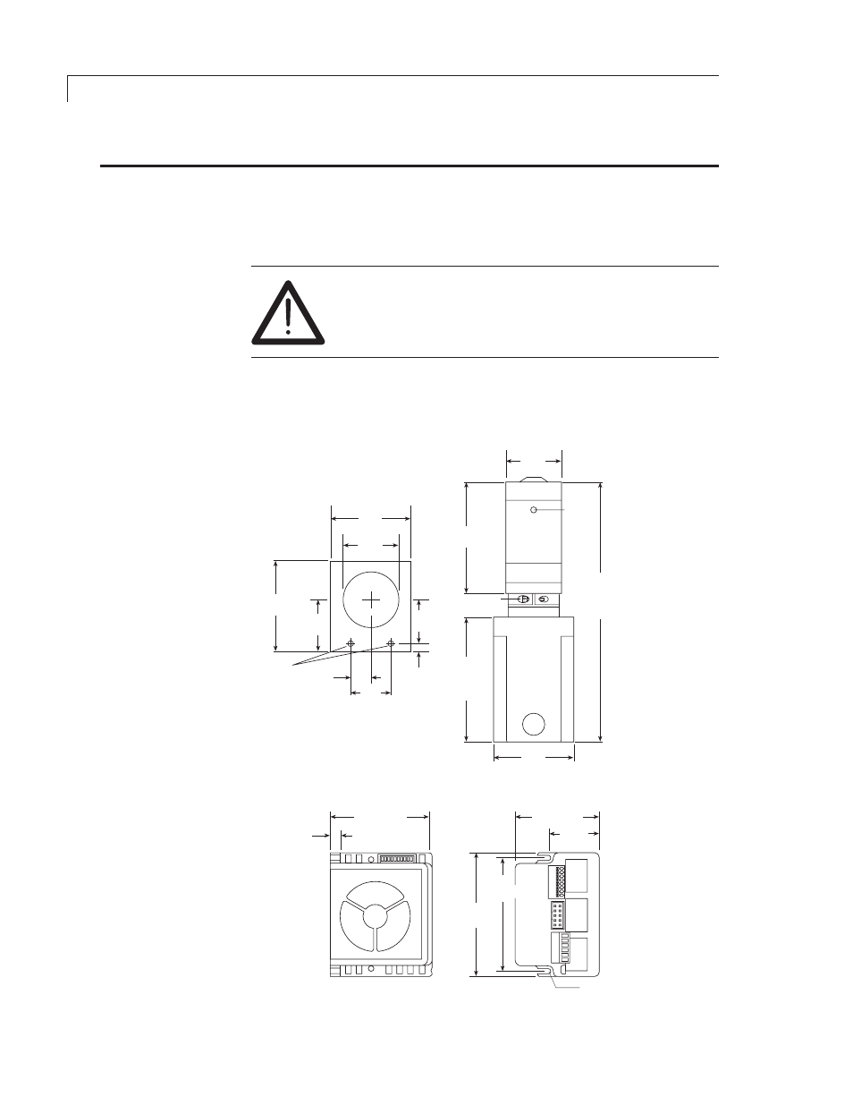
The mounting points of the pump motor and controller are given in
Figure 2,
along with the external dimensions of each module.
For best results, the M Series pump must be oriented
with its ports facing up. If the pump is oriented in any
other direction, bubbles may be trapped in the internal
chambers of the pump.
The controller should be mounted in such a way to allow adequate cooling.
If the cooling fan is obstructed the controller may overheat.
Figure 2: Mounting points and external dimensions
for the pump, motor, and controller
Pump and Motor Assembly
2.90"
(73.66 mm)
(
2 x .30"
(2 x 7.62 mm)
2.388"
(60.66 mm)
1.446"
(36.73 mm)
3.50"
(88.9 mm)
3.20"
(81.28 mm)
(
2 x 0.150"
(2 x 3.81 mm)
Controller
M6: 3.4"
(86.4 mm)
M50: 4.4"
(114.3 mm)
3.0"
(76.2 mm)
2.0"
(50.8 mm)
1.5"
(38.1 mm)
2.25"
(57.15 mm)
2.0"
(50.8 mm)
2.0"
(50.8 mm)
1.5"
(38.1 mm)
1.09"
(27.7 mm)
1.0"
(25.4 mm)
0.5"
(12.7 mm)
0.9"
(22.9 mm)
0.25"
(6.35 mm)
8-32 (2x)
CLAMP RING
SCREW
LEAK
PORT
M6: 7.1"
(180.3 mm)
M50: 8.1"
(205.7 mm)