Supply, control, and output connections – Tweco 7-4000 User Manual
Page 4
January 4, 2006
4
Manual 0-4739
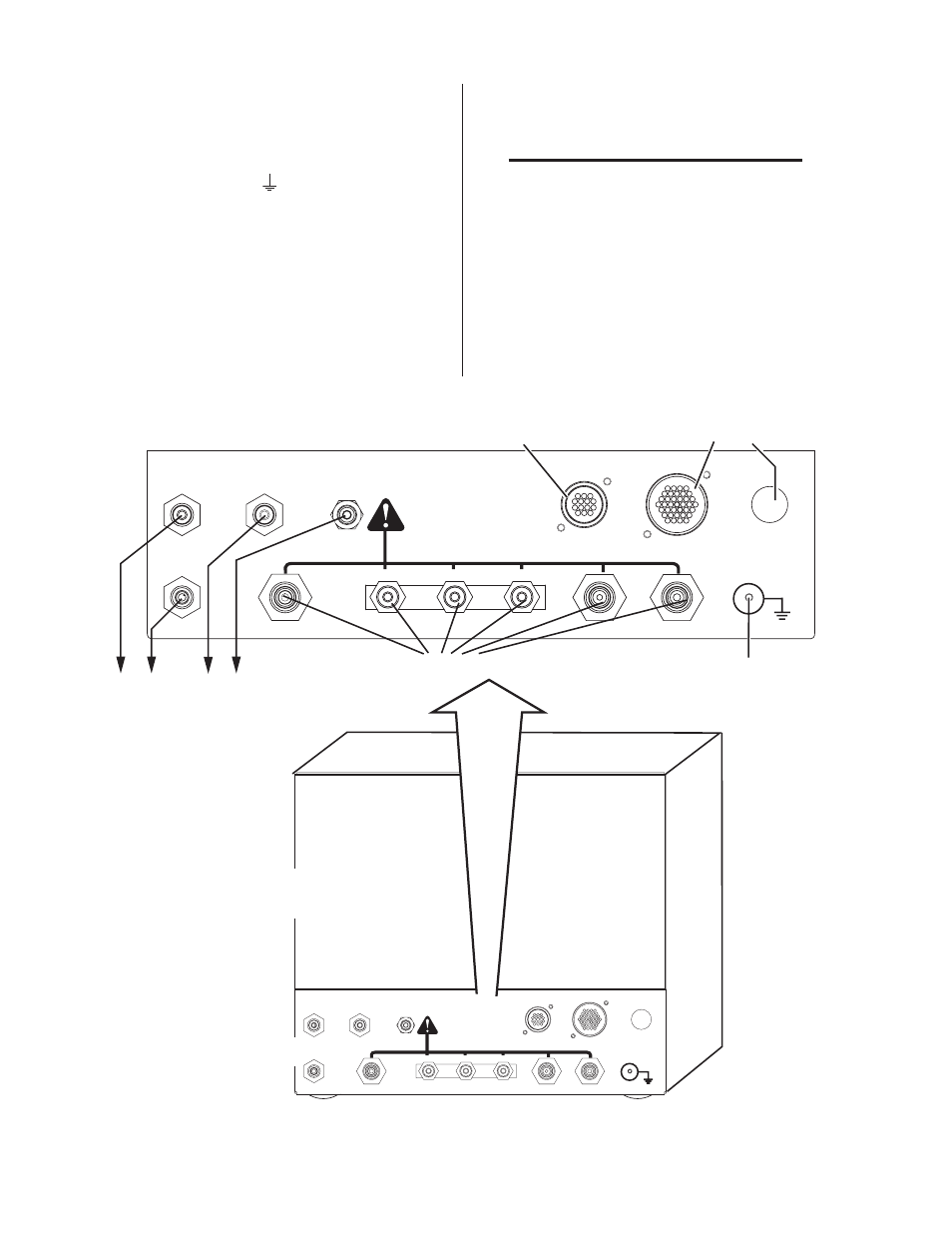
Supply, Control, and Output Connections
1 Make all other connections as required to the
rear of the module. The connections are labeled.
The module must be grounded; the grounding
terminal is marked . Use #10 AWG (or thicker)
wire for grounding. Keep the ground wire as
short as possible.
2. Position the module on a flat, horizontal sur-
face.
3. Ensure that the flowmeters are plumb.
4. Fasten the module to the mounting surface.
5. Connect inputs and outputs as shown.
NOTE
Water shield is not used in all applications.
NOTE
Every effort has been made to provide com-
plete and accurate information in this
manual. However, the publisher does not
and hereby disclaims any liability to any
party for any loss or damage caused by er-
rors or omissions in this manual, whether
such errors arise from negligence, accident,
or any other cause.
Gas & Water Inputs (Check Valves)
Connection Panel
To Torch Valve Assembly
To Torch Valve Assembly
To Power Supply
SHIELD
PLASMA
PREFLOW
H O
SHIELD
2
H O
2
AIR
N2
O2
H35
F5
TVA
POWER
SUPPLY
COMM
J57
J56
INPUTS
When Cutting With O2 Plasma
Air MUST BE Connected
Ground Stud
SHIELD
PLASMA
PREFLOW
H O
SHIELD
2
H O
2
AIR
N2
O2
H35
F5
TVA
POWER
SUPPLY
COMM
J57
J56
INPUTS
When Cutting With O2 Plasma
Air MUST BE Connected
Gas Control Box
Rear Panel
Art # A-06881