Tweco 7-3445 User Manual
Page 3
Manual 0-2773
3
Installation Instructions 8/21/01
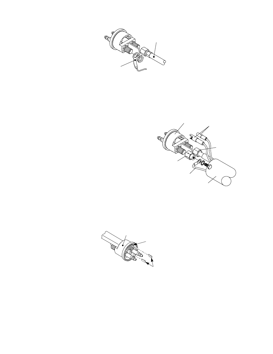
Negative/Plasma
Lead Connection
Pilot Lead
Connection
A-00031
Disconnecting Leads
11. Remove the protective boot, inner retaining ring and outer retaining nut from the old leads.
12. Discard the old leads and Signal Pin Connector.
B. Reassembling New Quick Disconnect
1. Slide the protective boot, inner retaining ring and outer
retaining nut from the old torch onto the replacement
torch leads.
2. Slide the supplied rubber insulator over the control con-
nector wires on the replacement torch.
3. Install the Pilot Adapter Fitting (left-hand threads) onto
the pilot fitting of the Quick Disconnect Body and tighten
securely.
4. Connect the pilot wire (+) from the replacement torch to
the Pilot Adapter Fitting and tighten securely with bolt
and washer provided.
5. Connect the Negative/Plasma Lead from the replace-
ment torch to the fitting on the Quick Disconnect Body
and tighten securely.
6. Insert the Signal Pin Connector in the quick disconnect
body and install the two white locking tabs on both sides. The bevel must be towards the signal connector.
Quick Disconnect
Body
Signal Pin
Connector
A-00164
White Tabs
Installing The White Locking Tabs
7. On the Signal Pin Connector connect the wires from the two mating connectors on the replacement torch
leads.
8. Slide the rubber insulator down over the control wires and the exposed end of the Signal Pin Connector.
Secure in place with the supplied Tie-Wrap.
9. Slide the outer retaining nut, boot, and inner retaining ring down onto the quick disconnect body.
10. Tighten the three set screws to secure the inner retaining ring onto the quick disconnect body.
Negative/Plasma
Lead
Pilot Lead
A-03009
Pilot Lead
Adapter
Torch Lead
Assembly
Quick Disconnect
Body
Torch Control
Connectors