Tweco 7-3445 User Manual
Page 2
Manual 0-2773
2
Installation Instructions 8/21/01
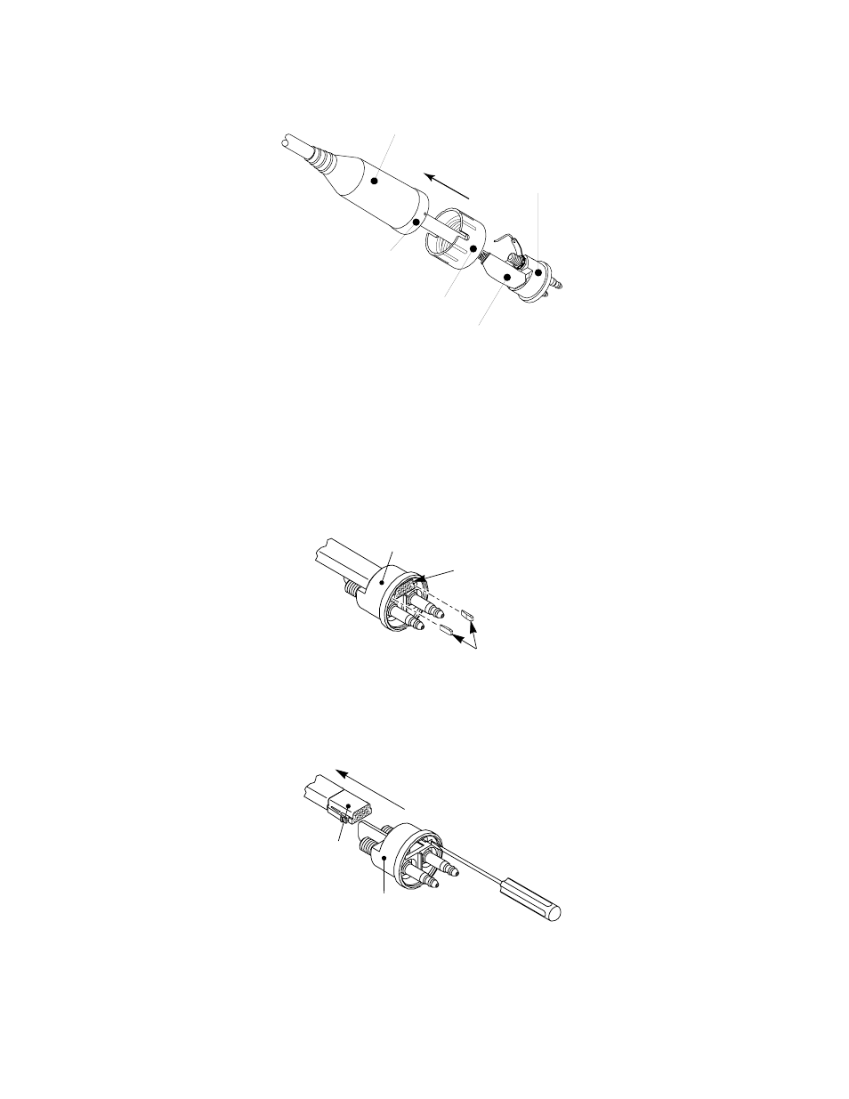
4. Pull the protective boot and inner retaining ring from the quick disconnect body.
Protective Boot
Outer Retaining Nut
Inner Retaining
Ring
Quick Disconnect
Body
A-00029
Rubber Cover &
Tie Wrap
Disassembly Of Connector
5. Slide the protective boot and inner retaining ring back over the torch leads to expose the leads connections.
6. Slide the outer retaining nut back over the leads.
7. Using a pair of needle nose pliers remove the two white tabs on each side of the signal connector. These tabs
hold the connector tightly in place to prevent it from moving.
Quick Disconnect
Body
Signal Pin
Connector
A-00164
White Tabs
Removing White Tabs
8. Using a small screwdriver, gently push in the tabs on the front of the Signal Pin Connector. Carefully push the
connector out through the back of the quick disconnect body.
Quick Disconnect
Body
Signal Pin
Connector
A-00030
Removing Signal Pin Connector
9. Cut all the wires connected to the Signal Pin Connector. The rubber boot cannot fit over the Signal Pin Con-
nector.
10. Disconnect the negative/plasma and pilot lead fittings.