Quick wire trim unit – Tweco QWT-3 Quick Wire Trim Unit User Manual
Page 9
QUICK WIRE TRIM UNIT
3-5
SM-QWT-3
INSTALLATION AND OPERATION
SECTION 3:
INSTALLATION AND OPERATION
1. Remove the QWT-3 wire trim unit from the shipping
carton. Check to ensure the assembled unit is complete
as shown in Figure 1. If any of the component parts
are missing, please notify the local Tweco Welding
Distributor or Tweco Products Customer Service
Department at 1-800-426-1888.
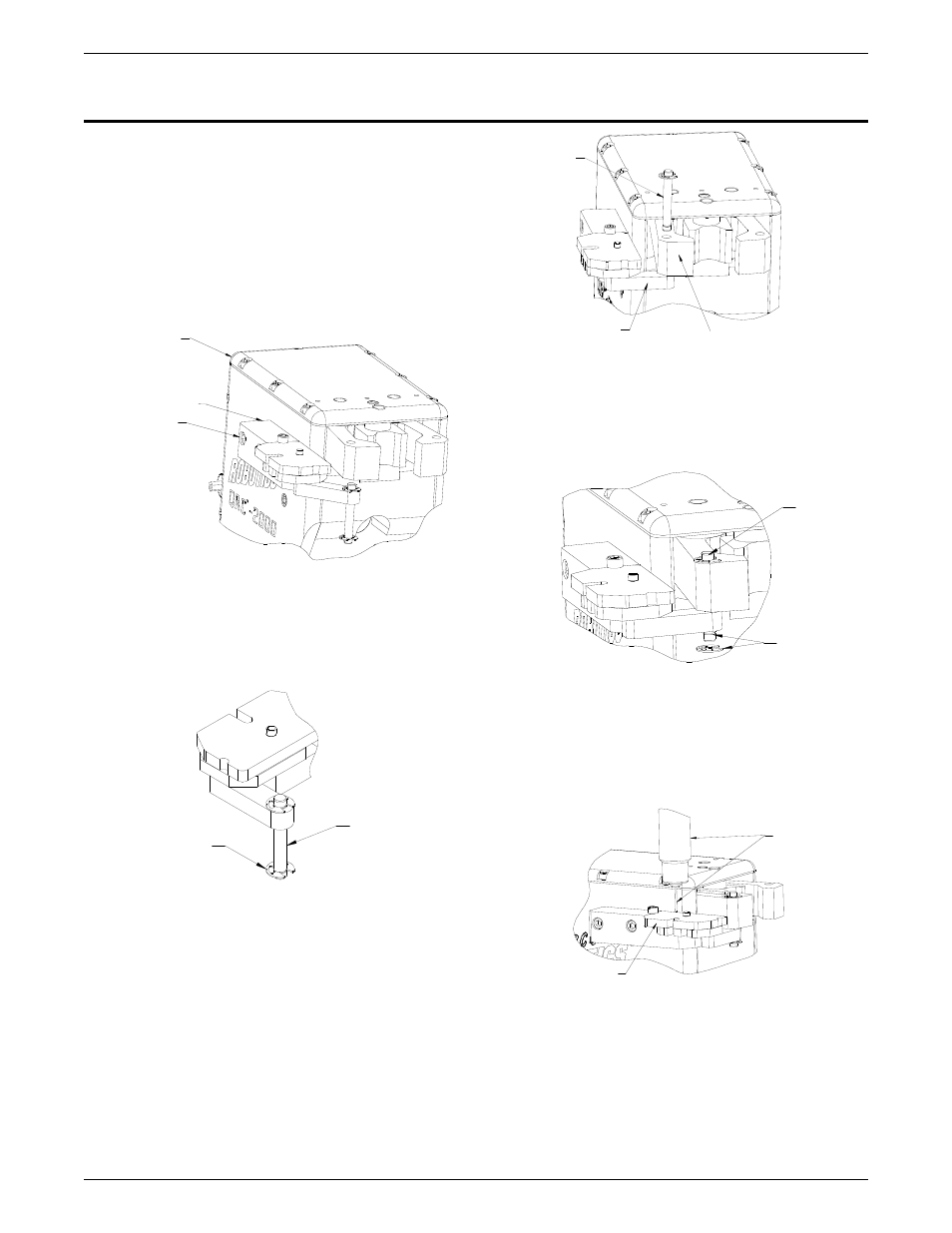
2. Mount the wire trim unit to the QRC™-2000 cleaning
station using a ¼”-20 x 1” long socket head, for the
cap screws supplied. Refer to Figure 2.
Figure 2: Wire Trim Unit Mounted on Cleaning Station
CLEANING
STATION
QWT-3 WIRE
TRIM UNIT
1/4”-20
SOCKET HEAD
CAP SCREW (2
EACH)
3. Remove the retaining clip from the pivot arm and move
the pivot arm toward the clamp arm of the cleaning
station. Refer to Figure 3.
RETAINING RING
PIVOT PIN
Figure 3: Retaining Clip on Pivot Pin
4. Position the pivot arm on the wire trim unit so that the
hole for the pivot pin is aligned with the ¼” (6,35mm)
hole in the clamp arm.
5. Insert the pivot pin through the pivot arm on the wire
trim unit and clamp arm of the cleaning station. Refer
to Figure 4.
PIVOT PIN
PIVOT ARM
CLAMP ARM
6. Hold the pivot pin in position so that the retaining clip
that was removed in Step 3 can be reconnected. Refer
to Figure 5.
Figure 4: Alignment of Pivot Pin, Pivot Arm and Clamp Arm
PIVOT PIN
GROOVE FOR
RETAINING
RING
7. Position the robot arm with the conductor tube
assembly directly above the wire trim unit. When
positioned correctly, the wire will be positioned
between the wire guide of the wire trim unit. Refer to
Figure 6.
Figure 5: Pivot Pin in Place
Figure 6: Conductor Tube/Wire and Wire Trim Unit
CONDUCTOR
TUBE NOzzLE/
WIRE
WIRE GUIDE
8. Lower the robot arm and conductor tube assembly to
a height that will expose the correct amount of welding
wire after cutting occurs — the welding wire should
extend past the cutting blade on the wire trim unit. Refer
to Figure 7.