Quick fixed automation direct plug torches, 01 installation – Tweco QFW600 User Manual
Page 10
quick fixed automation direct plug torches
3-6
SM-QFDP
inStAllAtion AnD oPeRAtion
SECTION 3:
INSTALLATION AND OPERATION
3.01 Installation
1. Remove the torch assembly from the carton.
2. Check to ensure all items, shown in Figure 1A or 1B are
located and identified. If any of the component parts
are missing, please notify the local Tweco Welding
Distributor or Tweco
®
Products Customer Service
Department at 1-800-426-1888.
3. The torch assembly comes with the Miller
®
rear
connector plug installed. If the feeder requires a
different rear connector plug, select the correct rear
connector plug for the feeder being used and thread
the plug into the rear of the cable assembly. This
connection should be wrench tight.
4. The QF Series torch assemblies are furnished with
R45-116 conduit and the rear connector plugs to fit
this series of conduit. If a different conduit and rear
connector plug is required, refer to Section 5, page
5-9 and 5-10, listing the various conduits that are
available.
5. Remove the conduit from the package.
CAUTION
bending or distorting the conduit can cause
wire feed problems.
6. Loosen the set screw located on the Tweco, Panasonic
®
and Lincoln
®
rear connector plug to ensure the conduit
will feed through properly. For Miller
®
style plug,
remove the threaded connector plug nipple from the
rear connector plug on the torch assembly. Refer to
Figure 2A & 2B.
8. When the conduit is completely through the torch
assembly, seat the brass conduit stop firmly against
the connector plug.
9. Tighten the set screw on the Tweco
®
, Panasonic
®
, and/
or Lincoln
®
rear connector plug. For Miller
®
style rear
connector plug, re-install the threaded connector plug
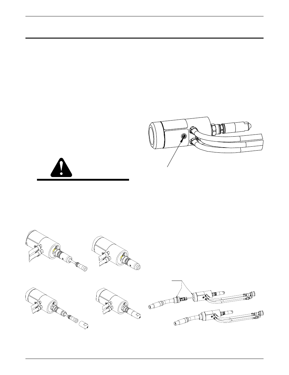
nipple. This connection should be wrench tight.
10. Locate the hole in the torch case providing access
to the conductor tube locking set screw. Insert the
factory supplied 5/32” T-handle allen wrench into the
set screw and rotate counterclockwise until it stops.
Refer to Figure 3.
Figure 2A: conduit installation With Set Screw
Figure 2b: conduit installation With Plug nipple (Miller
®
Style)
7. Insert the exposed raw coil end of the conduit, factory
supplied, into the rear connector plug. Feed the
conduit through the torch assembly.
Figure 3: Conductor Tube Locking Set Screw
11. Remove the gas diffuser, tip and nozzle from the
conductor tube assembly.
12. Insert the conductor tube assembly into the torch
block assembly. The conductor tube is positively
located into the torch body by the use of two stainless
steel alignment pins.
13. Push the conductor tube assembly into place until the
stainless steel set screw can drive the back plug on
the conductor tube into its locked operating position.
The conductor tube has a machined locating groove
around its rear diameter. This groove will be flush with
the front housing when properly installed as shown
in Figure 4.
WHEN CONDUCTOR TUBE IS FULLY
SEATED, GROOVE ON TUBE SHOULD
LINE UP WITH EDGE OF INSULATING
SLEEVE.
Figure 4: Conductor Tube Installation
SET SCREW (5/32” ALLEN KEY)