09 install wire into the welding gun, Install wire into the welding gun -5, Installation firepower fp-95 – Tweco FP-95 Mini MIG User Manual
Page 25
INSTALLATION
FIREpOwER Fp-95
Installation
3-5
Manual 0-5122
3.09 Install Wire into the Welding Gun
1. Plug the Welding Power Source into the 120VAC
receptacle.
WARNING
ELECTRIC SHOCK CAN KILL! With the gun
switch (located on the gun) activated, weld-
ing power is applied to the output terminals,
feedroll, ground clamp, gun cable connection
and welding wire. Do not touch these parts
with the gun switch activated.
2. Turn the welding machine ON with the front panel
Voltage Power Switch set to "Min"
MIN
MAX
Art # A-09073
Figure 3--7: Power ON
3. Set the wire feed speed to half-way or "5".
MIN
MAX
Art # A-09073
Figure 3-8: Wire Speed Half-way
4. Straighten the gun cable. Remove the nozzle and
contact tip from the MIG welding gun (see Section
2.08).
WARNING
If ground connection clamp is in place on the
workpiece the electrode wire is electrically
“hot” when the gun switch is activated.
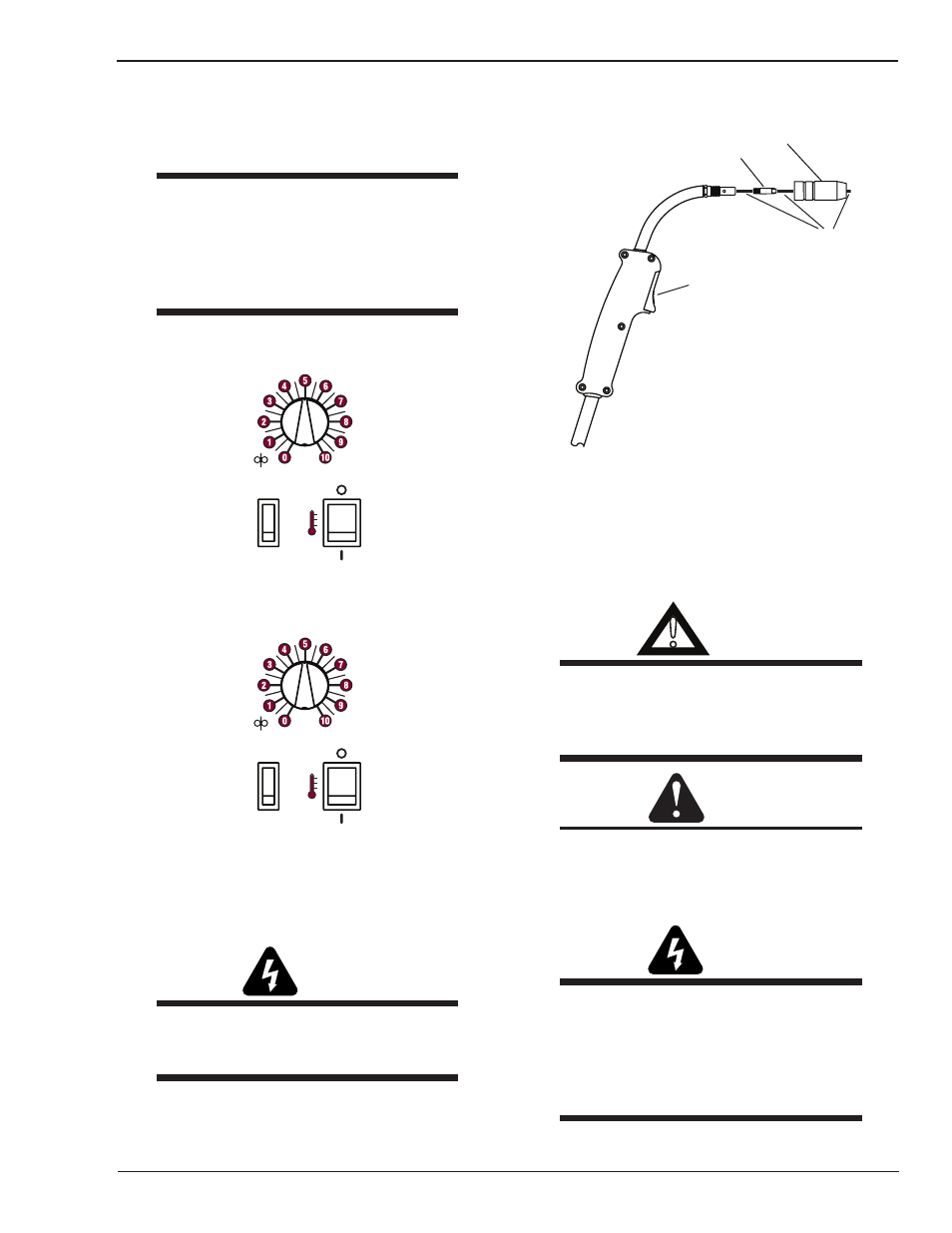
5. Activate the gun switch until the wire feeds
out past the gun nozzle and deactivate the gun
switch.
Contact Tip
Nozzle
Gun Switch
Wire
Art # A-09074
Figure 3-9: Feed Wire Through Gun
6. Set the Voltage Power Switch to "OFF" and unplug
the supply cord.
7. Replace the contact tip and nozzle. Cut the wire
within ¼” (6mm) from the nozzle.
!
WARNING:
The drive rollers, when moving, may crush the
fingers. Periodically, check the drive rollers.
Replace them when they are worn and com-
promise the regular feeding of the wire.
CAUTION:
The FP-95’s welding torch is a “live” contact
torch and is ALWAYS in the power on position.
Wear eye protection at all times when handling
this torch.
WARNING
ELECTRIC SHOCK CAN KILL! With the gun
switch (located on the gun) activated, weld-
ing power is applied to the output terminals,
feedroll, ground clamp, gun cable connection
and welding wire. Do not touch these parts
while the gun switch is activated.