T1 t2 – Tweco 500SP PowerMaster User Manual
Page 32
POWERMASTER 320SP, 400SP, 500SP
3-6
March 16, 2007
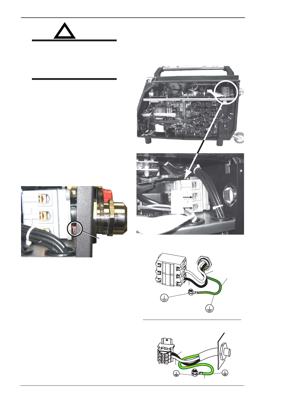
Connect input conductors as shown in illustration.
Connect green or green/yellow grounding
conductor to welding power supply grounding
terminal first.
Then connect input conductors T1 and T2 to
welding power supply line terminals.
On the 320SP, push the terminal block back on
the switch shaft and pull the red level toward you.
Reinstall side panel onto welding power supply.
C. Turn the Line Disconnect Switch off
D. Connect the green or green/yellow-grounding
conductor to the Line Disconnect Switch ground
terminal first.
E. Connect input conductors T1 and T2 to the Line
Disconnect Switch terminals.
1-Phase Input Power Connection
PowerMaster 400SP,500SP
1-Phase Input Power Connection
PowerMaster 320SP
GND/PE
GND/PE
GND/PE
GND/PE
L1
L1
L2
L2
L3
L3
Black
Black
White
White
Green & Yellow
Green & Yellow
Art # A-07862
T1
T2
!
WARNING
Never connect the safety ground screw to
one of the three line phases. This would
represent a serious electrical shock
hazard. The wiring to this machine should
be performed by a qualified person only.
A. Input Power Conductors (Customer Supplied
Cord)
Select size of conductors using table. Conductors
must comply with national, state, and local
electrical codes. If applicable, use lugs of proper
amperage capacity and correct hole size.
B. Welding Power Source Input Power Connections
Remove the side panel next to the strain relief.
Route conductors (cord) through strain relief and
tighten the compression fitting.
On the 320SP, disconnnect the terminal block from
the switch shaft by pushing the small red lever
away from you (see below).
Push red lever
away from you
to release the
terminal block
Art # A-07920
F. Select type and size of over-current protection
using table (fused Line Disconnect Switch shown).
G. Close and secure door on Line Disconnect Switch.
H. Remove lockout/tagout device, and place switch
in the On position.