Maintenance, Cleaning of the unit, Cleaning of the feed rolls – Tweco Hefty II CC CV Voltage Sensing Wire feeder User Manual
Page 30: Feedhead maintenance, Contactor maintenance, Gas valve maintenance
MAINTENANCE
Cleaning Of The Unit:
About every 6 months, remove the exterior cover
to expose the printed circuit boards and other com-
ponents. Using a vacuum cleaner or clean, dry,
compressed air of not more than 25 psi (172 kPa)
pressure, vacuum or blow out the interior of the wire
feeder
.
While the exterior cover is removed, check
all electrical components for loose connections and
correct if necessary.
Cleaning Of The Feed Rolls:
About every 3 months, clean the grooves on the
feed rolls using a small wire brush
.
If the feed roll
has a smooth surface, wipe off the feed roll with a
clean, dry cloth
.
After cleaning the feed rolls, tighten
the upper and lower feed roll retaining knobs ac-
cordingly.
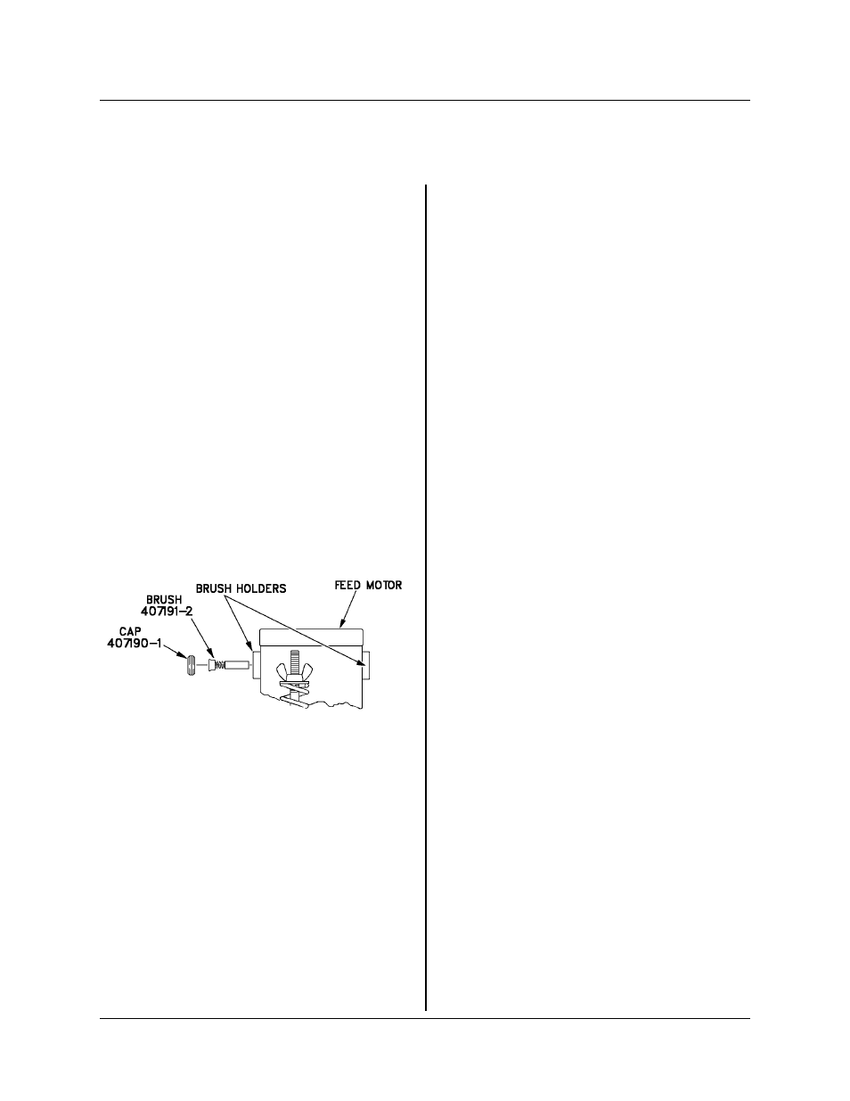
Feedhead Maintenance:
See Figure 6-1 for details.
The only point of maintenance in the feedhead
assembly is the motor brushes
.
Inspect these about
every 400 hours of operation
.
When either brush is
worn to about 1/4" (6.35 mm), both brushes should
be replaced.
CAUTION: Neglect in brush mainte-
nance may cause damage to the drive
motor commutator resulting in a shorter
motor operating life.
Contactor Maintenance:
Regularly examine the contacts on the contactor
.
When any contact is worn down to the copper bus
bar, the contactor should be replaced
.
Gas Valve Maintenance:
See Figure 6-2 for details.
Foreign material inside the valve body is the major
cause of gas valve failure or improper operation.
Foreign material usually enters the valve body when
disconnected gas lines are allowed to come in
contact with the floor or ground before being con-
nected or reconnected to the gas valve.
In general, sluggish operation and/or gas leakage
are signs the gas valve needs to be cleaned inter-
nally. To clean the gas valve internally, follow these
simple steps:
NOTE: Before disassembly of the gas
valve, take note of the orientation of inlet
(marked IN) and outlet ports with respect to
electrical connections. The reassembled
gas valve should have the same orienta-
tion.
1. Remove input power from the wire feeder, and
depressurize the gas valve.
2. Remove the gas valve from the wire feeder.
3. Remove the (2) bracket screws and bracket
from the yoke of the gas valve.
4. Slip the yoke (containing coil) off the plug-
nut/core tube sub-assembly.
5. Remove the plugnut/core tube sub-assembly
with the body gasket attached.
6. Remove the core assembly and core spring.
7. All parts should now be inspected for foreign
material and cleaned with a lint-free cloth. Do not
nick or scratch any internal parts of the gas valve.
8. Reassemble the gas valve in reverse order of
disassembly paying careful attention to Figure 6-2.
NOTE: Tighten (2) bracket screws evenly
to insure proper body gasket compression.
Torque bracket screws to 20 inch-pounds.
9. Assemble the gas valve to the wire feeder.
NOTE: It may be necessary to apply pipe
compound sparingly to the gas adapter
male threads only. Do not apply compound
to female threads of gas valve or first two
threads of male fittings. Also, make sure the
Figure 6-1
430429-456
MAINTENANCE
June 5, 2000 Revised
6-1