05 connecting torch, 05 connecting torch -2 – Tweco Max 300 w-Merlin 6000GST User Manual
Page 20
INSTALLATION
3-2
Manual 0-2642
3.05 Connecting Torch
WARNING
Disconnect primary power at the source before dis-
assembling the torch or torch leads.
The Torch Leads connect directly to a bulkhead inside
the Arc Starter Box. Connect the Torch Leads per the fol-
lowing procedure:
NOTE
The Arc Starter Box must be installed in the sys-
tem according to the Arc Starter Box Instruction
Manual, 0-2654 supplied with the Arc Starter Box.
1. Remove the cover from the Arc Starter Box if in-
stalled.
2. Remove the tape securing the shield of the torch
leads to the leads.
3. Unfold the shield towards the end of the leads.
4. Feed the Control Cable through the boot on the
end of the Arc Starter Box.
5. Feed the torch leads through the boot on the torch
end of the Arc Starter Box.
A-01775
Torch Leads
Hose Clamp
Shield Braid
Torch Leads
Shield Assembly
(Brass Hub)
Control Cable
Figure 3-2 Hose Clamp
6. Feed the Control Cable and torch leads through
the supplied Hose Clamp.
7. Connect the Control Cable to the mating connec-
tor on the Center Chassis.
Control Cable
Control Cable
Connector
A-01774
Figure 3-3 Control Cable Connection
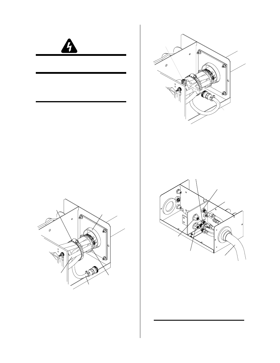
8. Connect the torch leads connectors to the bulk-
head connections per the following figure.
A-01776
Torch Leads
Secondary Gas
Plasma Gas
(Left-Hand Thread)
Coolant Supply
Coolant Return
(Left-Hand Thread)
Pre-Flow (N2)
Gas
Figure 3-4 Torch Leads Connections
9. Pull the shielding braid towards the end panel as
far as it will go up and over the brass hub. The
hub is part of the Boot Assembly and provides
the grounding point for the shielding in the torch
leads.
NOTE
The shielding braid must not make contact with
the four mounting studs.