Hand-held operation – Triton JOF 001 User Manual
Page 7
7
GB
Functions / Hand-Held Operation
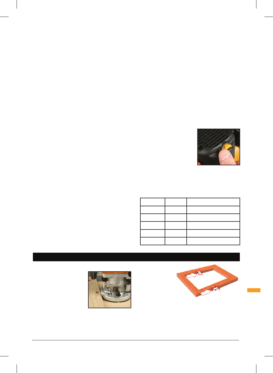
HAND-HELD OPERATION
• Put on all safety equipment required to use this tool
• Ensure your workpiece is
securely clamped to prevent
any movement during
operation
• Hold the router firmly using
both hands to control the
router and keep an even
pressure and movement
when cutting
• Never operate the router freehand without some form
of guide. Guidance can be provided by a bearing guided
cutter, the fence guide supplied, or a straight edge
• Always feed against
the direction
of cutter
rotation. The
cutter rotates
clockwise (as
indicated by the arrows
on the base adjacent to
the
baseplate
mounting knobs)
• Do not operate the router upside down unless securely
mounted in a well guarded router table (for example,
the Triton Router Table)
2. Insert the router bit fully into the collet, then use the
spanner to tighten the collet so that it holds the bit firmly
3. Hold the body of the machine securely and disengage
the plunge lock lever. This will release the collet lock
and the power lock out cover
DUST EXTRACTION
Dust Port
• The Triton JOF Router is equipped with a Dust
Extraction Port (6) for chip extraction above the cut.
It accepts 38mm (1-½") O.D. hose, supplied with the
Triton Dust Collector (DCA300)
• The hose screws into position via a left hand thread
(anticlockwise)
DEPTH STOP & TURRET
• The Depth Stop (11) and Turret (9) enable accurate pre-
setting of two different cut depths
Zeroing the router
1. Fit the router bit you require and place the router, right
side up, on the work bench
2. Rotate the Turret (9) until the fixed post is beneath the
depth stop
3. Loosen the Depth Stop Lock Knob (11) so that the
depth stop is fully released
4. Release the Plunge Lock Lever (7), then plunge the
router until the tip of the bit is in contact with the
surface of the work bench
5. Now tighten the depth stop lock knob so that the depth
stop is locked in its current position
Pre-setting the cut depths
1. The top of the fixed post now provides an accurate
datum, and the depth of cut can be set by reference to
the graduations printed on the side of the fixed post
2. To set a cut depth, rotate the thumbwheel on one of the
Turret Stops (9) until the top of the thumbwheel aligns
with the depth of cut required (as shown on the fixed
post) For example, for a cutting depth of 3mm, rotate
the thumbwheel until the top is aligned with the 3mm
mark on the fixed post.
3. To pre-set a second depth, repeat the procedure with
the second thumbwheel
Plunging to pre-set depth
• Rotate the turret until the thumbwheel at the required
depth is positioned beneath the depth stop
• Now, when you plunge the router, the depth stop will
hit the thumbwheel and retain the router at the precise
depth required
VARIABLE SPEED CONTROL
• Router speed settings are not critical - generally the
highest speed which does not result in burn marks on
the workpiece should be used. Where stated, always
follow the cutter manufacturer's maximum speed
limitations
• Generally, higher speeds are
used for timber and MDF,
lower speeds for synthetic
materials
• Operating at reduced speed
increases the risk of damage
to the router as a result of
overload. At low speeds use
very slow feed rates and/or
multiple shallow cuts
• The Speed Controller (1) is marked 1 to 5, corresponding
approximately with the speeds and cutter diameters
below. Turn the dial to select the speed required
Setting
RPM
Cutter Diameter
5
20,000
Up to 25mm (1")
4
18,000
25 – 50mm (1" – 2")
3
14,500
50 – 65mm (2" – 2-
1
⁄
2
")
2
11,000
Over 65mm (2-
1
⁄
2
")
1
8,000
Use only if burning
925837_Z1MANPRO1.indd 7
13/11/2013 16:46