Trebor 610RC Magnum User Manual
Page 16
Page 16
M610RC
8100 South 1300 West, West Jordan, Utah 84088 USA Tel: 801-563-0303 Fax: 801-255-2312
www.treborintl.com
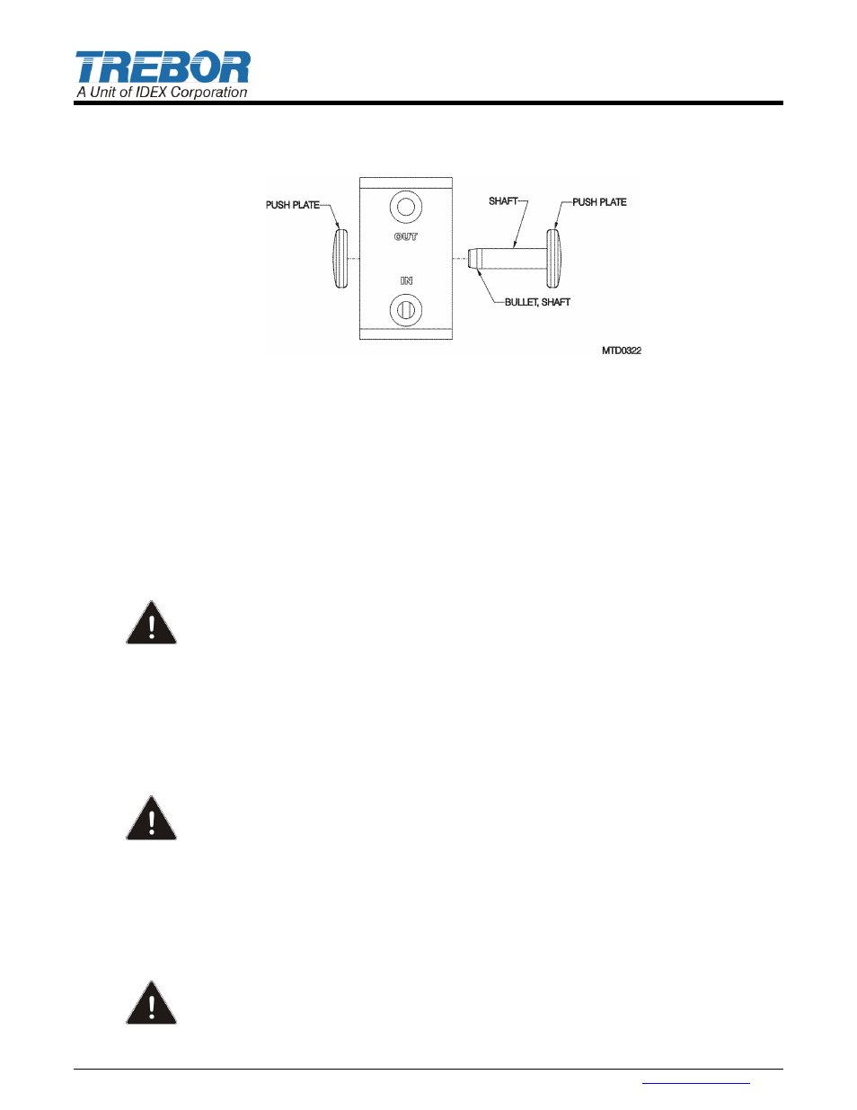
Thread shaft into push plate, gently snug.
Insert shaft through shaft bore using shaft bullet as shown (This prevents damage to the PTFE shaft
seals).
Figure 6-3
6.8.c
Final Assembly
Remove bullet and thread on remaining push plate, gently snug.
Insert tie bolt assemblies through slave head and lay flat with tie bolts sticking up.
Place main seal O-ring into the main seal groove in slave head.
Install a diaphragm set, removing all air from between diaphragms, onto the tie bolts noting the
relative orientation of the formed main seal groove in the diaphragms with respect to conforming to
the main seal. Also note air transfer port hole alignment.
Place one main transfer tube with seal into respective port.
Place pilot transfer tube and one seal into slave head.
Install one conductive pin in the slave head.
CAUTION: If conductive pin is not properly installed, it may pose a risk to personnel, equipment
or environment, when operating in areas with explosion hazard.
Carefully place and press the body assembly onto the tie bolts, transfer tubes, seals, and slave head.
Install the remaining diaphragm set onto the tie bolts and body, again noting formed main seal groove
and transfer port seals (O-rings).
Install seal onto protruding pilot transfer tube.
Place the master side main seal O-ring into the formed groove in the diaphragms as closely as
possible to ensure engagement into the main seal groove in the master head.
Install one conductive pin in the master head.
CAUTION: If conductive pin is not properly installed, it may pose a risk to personnel, equipment
or environment, when operating in areas with explosion hazard.
Place remaining main transfer tube and seal into body.
Install the master head onto the bolts taking care not to jar or move any of the mating components.
Install flange nuts onto tie bolts; tighten to 42 in-lbs. torque.
Install tie bolt caps and check muffler assembly.
Install pump onto base and slide back. Use locking lever to secure.
Resistance between heads must be less than 1,000,000 ohms.
CAUTION: A good validation of correct pump assembly is to check the resistance between
both pump heads to ground. Failure to assemble properly may pose a risk to personnel,
equipment or environment, when operating in areas with explosion hazard.