5 parts list, 6 clean-up, 7 disassembly – Trebor 610RC Magnum User Manual
Page 13
M610RC
Page 13
8100 South 1300 West, West Jordan, Utah 84088 USA Tel: 801-563-0303 Fax: 801-255-2312
www.treborintl.com
6.5
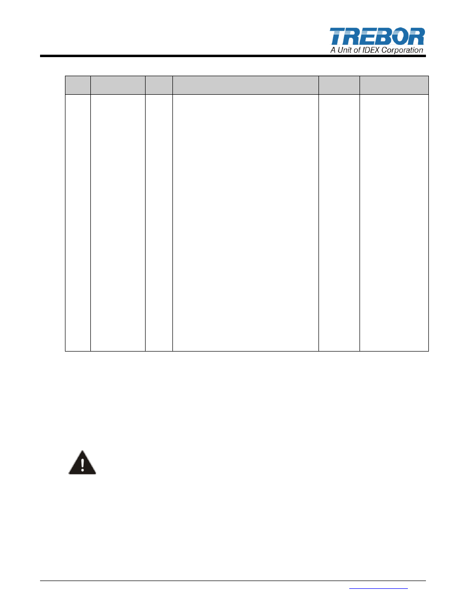
PARTS LIST
ILL
NO
PART NO
QTY
DESCRIPTION
PM
YEAR #
MATERIAL
1
1100C0026
1
Shuttle Plug
PP
2
11001230
1
Detent
1 & 2
Acetal, SS
3
11001210
1
Shuttle Assembly
1 & 2
SS410, Buna
4
C0135
1
Check Muffler Assembly
2
PP, NPRN
5
98001109
12
Tie Bolt Cap
2
PU
6
98002338
6
Nut, Flanged
SS18-8
7
C0142
1
Master Head
PP
8
11001220
2
Pilot Valve
Brass, SS, NBR
9
98003600
2
Main Seal
2
Viton
10
C0100
2
Diaphragm Set
2
PFA
11
C0095
2
Push Plate
PTFE
12
1610B0022
1
Shaft
2
PFA
13
98001976
2
Shaft Seal
2
PTFE
14
C0141
1
Body
PTFE
15
98002334
4
O-Ring, PTFE Check Valve
2
PTFE
16
98001415
4
Check Ball
2
PTFE
17
1610B0007
2
Suction Sleeve
PTFE
18
1610B0008
2
Discharge Sleeve
PTFE
19
AM084
2
Seal, Check Bore Cap
2
PTFE
20
C0144
2
Check Bore Cap
PTFE
21
C0143
1
Slave Head
PP
22
1610B0010
6
Tie Bolt Assembly
SS416, PFA
23
AM022
1
Mounting Base
PP
24
98003207
4
Mounting Screw
PP
25
98003071
1
Locking Lever Screw
PP
26
AM023
1
Locking Lever
PP
27
C0102
1
Quick Release Base
PP
28
1610A0013
1
Pilot Transfer Tube
PFA
29
98002331
2
O-Ring, Transfer Tube
2
Viton
30
1110A0022
2
Main Transfer Tube
PFA
31
98002332
2
O-Ring, Transfer Tube
2
Viton
32
98003599
2
Conductive Pin
SS
33
C0145
1
Conductive Connector Group
SS
6.6
CLEAN-UP
The pump fluid cavities may be flushed clean by cycling with the suction (IN) and discharge (OUT) lines
connected to a DI water flushing or rinsing tank. Flushing using an external pressure source without
allowing the pump to cycle will result in incomplete removal of potentially dangerous chemicals.
6.7
DISASSEMBLY
During the life of the pump it will be necessary to perform certain preventative maintenance procedures to
ensure its continued high performance operation. This section and the next (6.8 Assembly) are provided
for the user’s convenience in disassembly and re-assembly procedures.
CAUTION: Pump assembly and disassembly must be performed by authorized and qualified
personnel who have fully read this manual. If not, the pump could be damaged and people and
the environment placed at risk when operating this pump in explosive hazard areas.
Thoroughly clean / flush the pump using DI water (Refer to Section 6.6 Clean Up).
Unlock pump from quick release base by pulling out locking lever on front of base. Then slide pump
forward until it stops. Lift pump off base.
Remove check muffler assembly.
Remove tie bolt caps from both heads.
Remove flanged nuts from the tie bolt assemblies. (Master Head side.) Using both 3/8” nut drivers.
Leave tie bolts in place.
Lay the pump on the slave head side.