Front panel descriptions – Sound Devices 744T User Manual
Page 10
744T User Guide and Technical Information
4
v. 2.67
Features and specifications are subject to change. Visit www.sounddevices.com for the latest documentation.
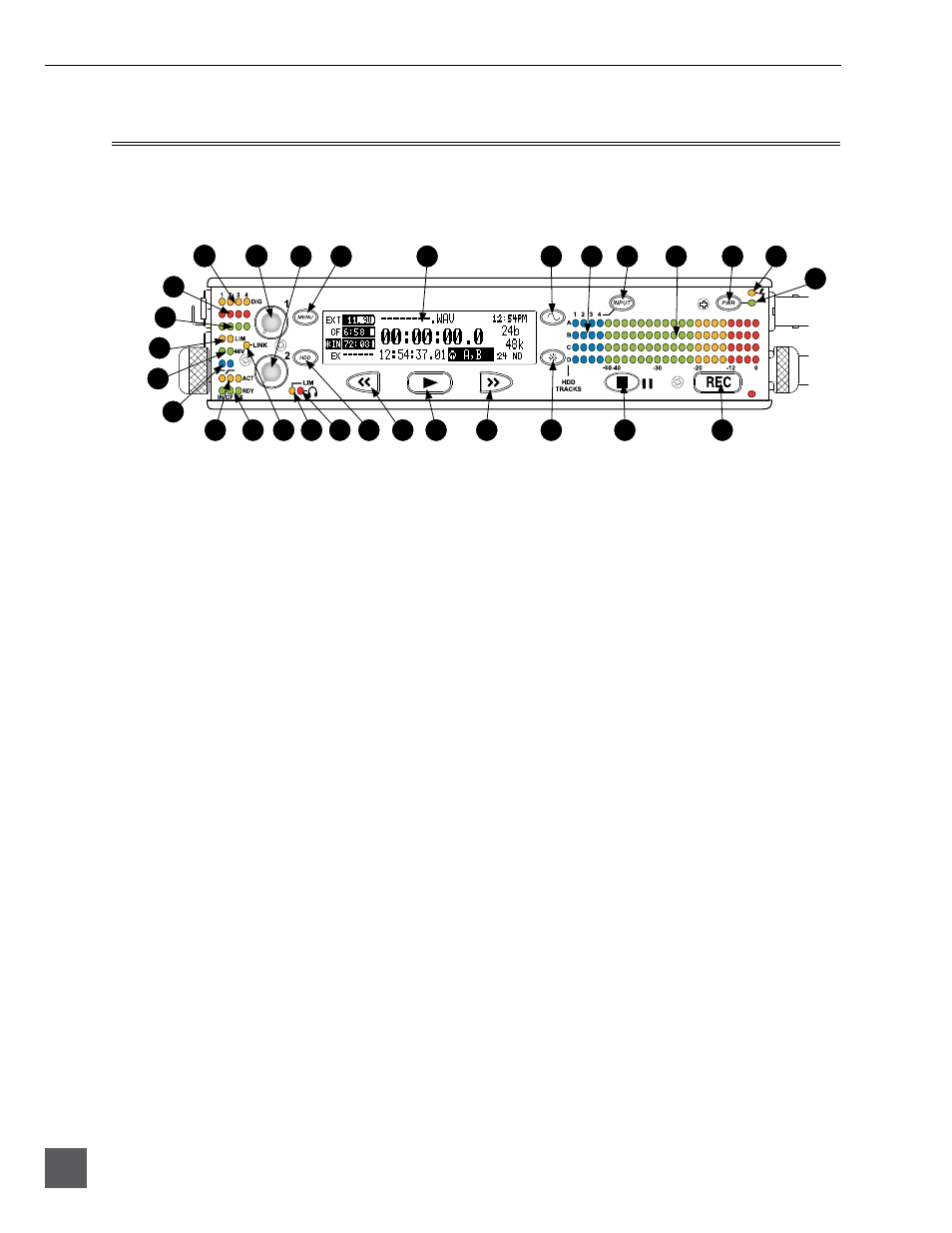
Front Panel Descriptions
All 744T settings can be accessed and monitored through the front panel LCD and navigation keys.
This allows the unit to be placed in a production bag along with field mixers and wireless transmit-
ters and receivers.
744T
14
20
21
22
23
24
26
27
28
29
5
6
15
16
17
18
19
25
4
2
1
10
13
7
8
9
3
12
11
1)
Digital Input LEDs
Indicates the presence of digital signal
on the respective input. When flashing,
indicates that digital input is selected
but no valid digital clock signal is pres-
ent.
2)
Input 1 Gain
Controls the analog gain (input trim) of
the channel 1 input. Normal mic input
range is from 25 dB to 70 dB, low gain
mic range is from 10 dB to 55 dB, line
input range is from
-
6 dB to 18 dB. For
line-level inputs, this control can be
defeated and gain can be setup menu-
controlled. If the LCD display shows
“locked” when the pot is turned, gain
control of the line-level input is menu-
controlled. When inputs are linked as
a stereo pair, Input 1 Gain controls the
gain of both inputs.
3)
Input 2 Gain
Controls input 2 gain, as in #2 above.
When inputs are linked as a stereo pair,
Input 2 Gain controls left-to-right bal-
ance.
4)
MENU Key
Used to access all 744T setup menu
selections. When in menu mode, used to
move up through the menu selections.
Pressing the HDD and MENU keys
simultaneously brings up the time code
jam menu.
5)
LCD Display
Primary display of 744T status. The
LCD is backlit using the LCD backlight
control (#15).
6)
Tone Oscillator
Press to activate the tone oscillator, press
and hold for two seconds or longer to
latch on, press again to deactivate. Fre-
quency, tone level, and routing are con-
trolled in the Setup Menu. When in the
Setup Menu use the TONE key to enter
Setup Menu options and select parame-
ters when the check mark appears in the
upper right hand corner of the LCD.
7)
Input-to-Track Matrix LEDs
Blue LEDs indicate inputs (1, 2, 3, 4)
enabled for recording to tracks (A, B, C,
D). A solid blue LED indicates an input
is routed to a track. A flashing LED dur-
ing “custom” routing mode shows the
selected input/track combination.
8)
INPUT Select Key
Pressing the INPUT key brings up the
input muting and routing menu. Hold
down the INPUT key and press one
of the four indicated soft keys to mute
inputs. Pressing the STOP key and the
INPUT select key cycles through the
six factory preset input-to-track routing
combinations plus the custom routing
menu. In the custom routing menu any
input can be routed to any track. (See
Input-to-Track Routing
)