Connection and setup connection and setup – SONIQ QSP320T User Manual
Page 8
Connection and Setup
Connection and setup
-13-
-14-
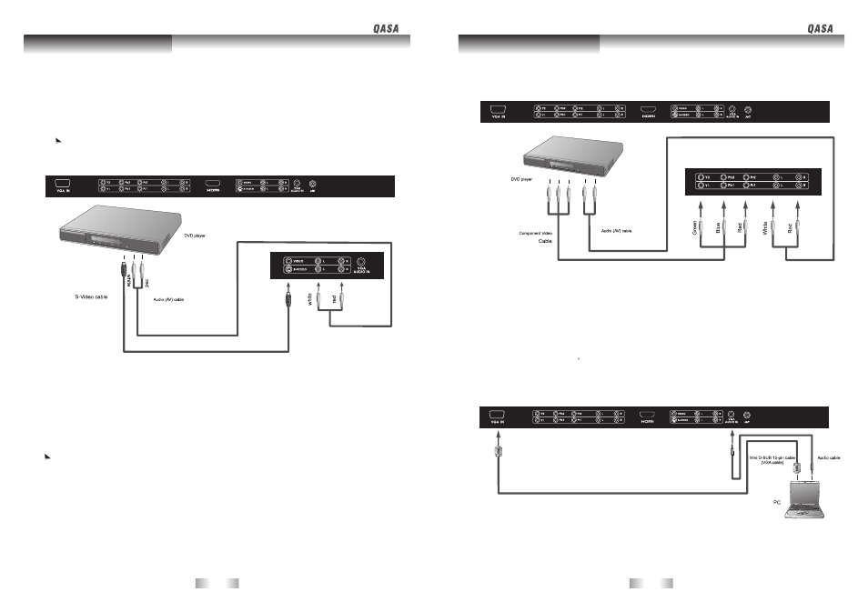
Connect the S-Video output of your AV equipment to the unit S-VIDEO terminal using an S-Video
cable. Pay attention to the direction of the connector on the S-Video cable when inserting.
Connect the audio output of your AV equipment to the unit S-VIDEO AUDIO L/R input terminal
using the AV cable or equivalent.
1.
2.
An S-video signal provides a higher quality image to that of Composite video. It is recommended
to use this input whenever possible. If your AV equipment provides a component video output
( YPbPr) or HDMI, this should be used in preference to either composite or HDMI signals.
Connect the Component video output of your AV equipment to the unit COMPONENT
YPbPr terminals using a Component video cable.(green,blue,red cable)
Connect the audio output of your AV equipment to the unit AUDIO L/R input terminals
using the AV cable or equivalent.
1.
2.
Of the currently available video signal types, Component video input offers the best quality.
Component video output is available on progressive scan DVD players and Digital television
decoders. The image quality with this type of input is superior to that obtained with S-video.
All High Definition Television signals must go through this input.
Ensure the connector colors match, failure to connect the colors of the cables to the
corresponding colored terminals will result in an incorrectly color image or badly distorted
image.
1.
2.
Connect PC video output to the VGA IN input terminal using Mini D-SUB 15-pin cable.
Connect the audio output of your PC to the unit VGA AUDIO IN input terminal using an appropriate cable.
If the input signal resolution is higher than the default display resolution, the screen may be unable
to display image details clearly.
Certain PC models cannot be connected to the unit.
The computer in the illustration is shown only for reference; your equipment may vary.
Additional equipment shown in the illustration is not provided.
Do not set the computer s horizontal and vertical scanning frequencies less than or greater than
the frequency range of the unit.(refer to Supported PC Input Signal )
If you require more information on how to connect your equipment, please refer to the manual for
the piece of equipment you wish to attach.
1.
2.
3.
4.
5.
6.
Connecting S-Video signals
Connecting Component Video signals
Connecting VGA signals