RCBS Pro 2000 Progressive Reloading Press User Manual
Page 5
- 5 -
4. Install the Bullet Tray with two 8-
32xl/4" socket head cap
screws(A). Attach two Ammo Bins
to the front of the Bullet Tray(B).
See photo 3
Photo 3
5. Slide the Bottle Cap over end of
Spent Primer Tube down to flared
end and attach Bottle to Cap.
Next, slide on the Return Spring
Plate with the squared section
pointed at the Bullet Tray as
shown in photo 4, then slide on
the Spring.
Photo 4
6. Raise the Ram to the top of the
press stroke and install the Return
Spring Plate, Spring, Spent Primer
Tube and Bottle assembly by
securing the setscrew at the
bottom side of the Shell Plate
Holder Assembly. NOTE: The
Return Spring Plate must rest on
top of the Press Frame. See photo
4 above.
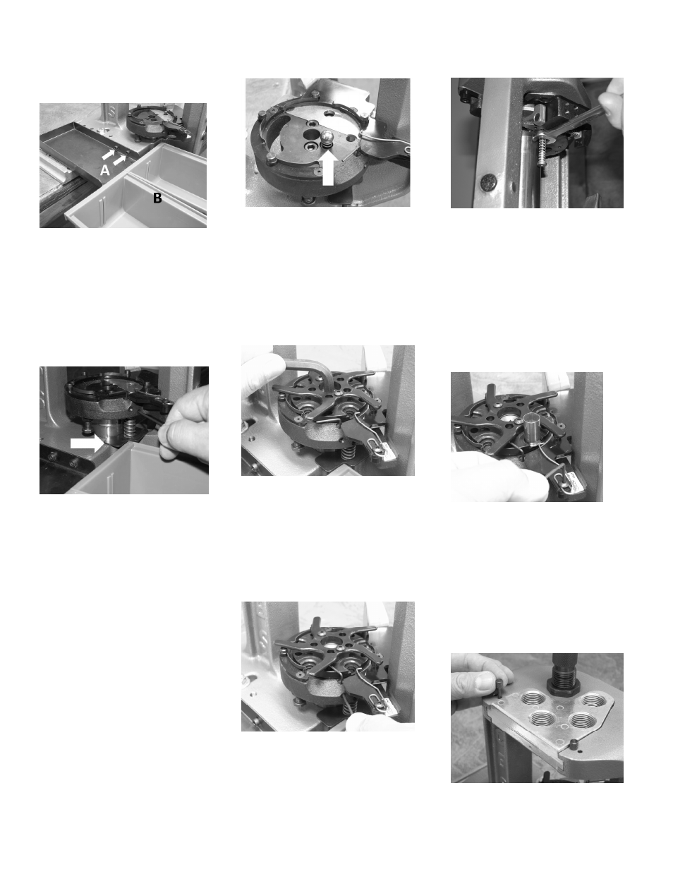
CALIBER SET UP
The following steps should be
completed for every caliber
changeover.
1. Install the Detent Spring and Ball
into Shell Plate Holder. See photo
5.
Photo 5
2. Attach Star Wheel to Shell Plate
using two 8-32x3/8” socket head
button screws.
3. Install the Shell Plate onto the
Shell Plate Holder assembly with
the Shoulder Bolt and 5/16” hex
wrench. See photo 6
Photo 6
4. Loosen the 5/64” SHSS in the
shell plate holder assembly and
adjust Case Eject Wire to point to
the rear of the shell holder slot.
Tighten SHSS using the included
5/64” hex key wrench. See photo
7.
Photo 7
5. The Small Primer Plug assembly
is factory installed. Replace with
the Large Primer Plug assembly if
desired.
6. Tighten the primer plug assembly
with a 7/16” open-end wrench
(not included). See photo 8.
Photo 8
7. Insert a case into station 1.
Loosen the 3/32” BHCS, adjust
station 1 case holder spring to
barely touch the rim of the case,
hold spring in place and tighten
BHCS. Use included 3/32” hex
key wrench. Remove the case.
See photo 9. NOTE: This
adjustment must be made each
time you change shell plates.
Photo 9
8. Thread in the Case Activated
Powder Measure assembly into
Station 3 of the Press Frame.
9. Install Die Plate and lock into
place with the two Die Plate Pins.
See photo 10. The two outside
holes are for pin storage when
Die Plate is removed.
Photo 10