Burnham SCG User Manual
Page 23
23
F.
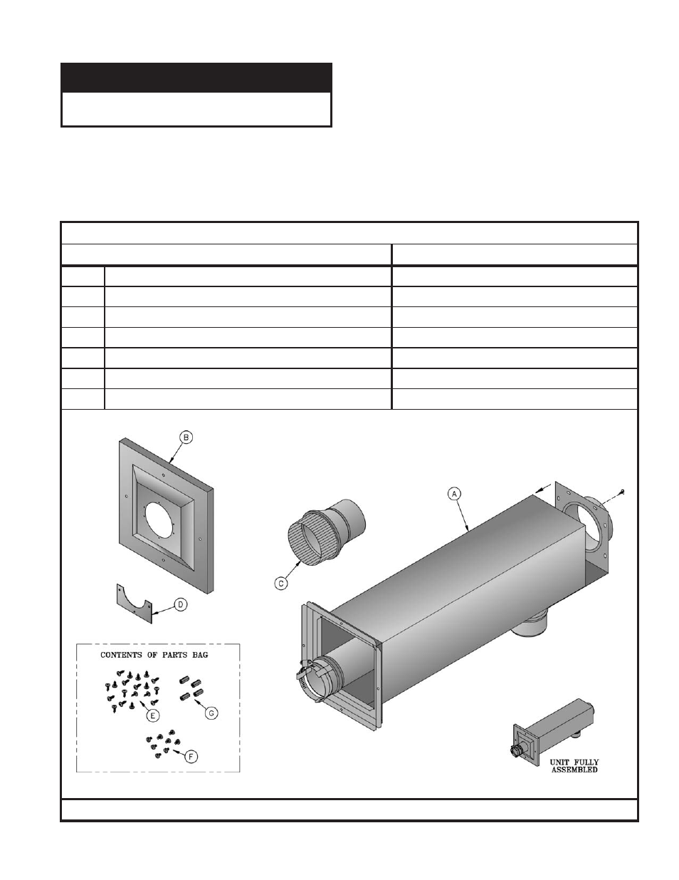
Combination Horizontal Venting System –SCG-3 Through SCG-6 ONLY – See Figures 10 and 11.
E
C
I
T
O
N
t
o
n
s
t
n
e
n
o
p
m
o
c
s
e
r
i
u
q
e
r
m
e
t
s
y
s
t
n
e
v
s
i
h
T
.
r
e
l
i
o
b
e
h
t
h
t
i
w
d
e
i
l
p
p
u
s
1. Do not exceed maximum vent/air intake lengths.
Refer to Table 4.
2.
Install Combination Vent/Air Terminal.
See Figure 11.
a. After determining the location with reference to Section B - General Venting Guidelines, cut a 6-1/8 inch square
opening in the wall for the air box sub-assembly which is 6 inch square.
b. Remove and save shipping screw from end panel with collar and vent pipe assembly. This will be reinstalled in a later
step.
2
1
0
6
0
1
1
6
r
e
b
m
u
N
t
r
a
P
n
o
t
r
a
C
t
n
e
V
)
w
o
l
e
b
s
m
e
t
i
s
e
d
u
l
c
n
i
(
n
o
i
t
p
i
r
c
s
e
D
r
e
b
m
u
N
t
r
a
P
t
n
e
n
o
p
m
o
C
A
)
g
n
o
l
'
2
x
e
r
a
u
q
s
"
6
(
y
l
b
m
e
s
s
A
-
b
u
S
x
o
B
r
i
A
1
1
0
6
0
1
1
6
B
)
e
r
a
u
q
s
"
0
1
(
r
e
v
o
C
ll
a
W
r
o
i
r
e
t
x
E
6
1
0
6
0
1
1
7
C
r
e
c
u
d
e
R
e
p
i
P
t
n
e
V
"
3
x
"
4
9
3
2
6
1
1
8
D
)
2
(
r
e
v
o
C
r
o
i
r
e
t
x
E
l
a
e
S
-
e
t
a
l
P
7
1
0
6
0
1
1
7
E
)
9
1
(
w
e
r
c
S
l
a
t
e
M
t
e
e
h
S
l
e
e
t
S
s
s
e
l
n
i
a
t
S
"
½
x
8
#
7
4
0
0
6
8
0
8
F
)
8
(
w
e
r
c
S
e
n
i
h
c
a
M
l
e
e
t
S
s
s
e
l
n
i
a
t
S
"
¼
x
2
3
-
0
1
#
2
4
8
0
6
8
0
8
G
)
4
(
r
e
c
a
p
S
m
u
n
i
m
u
l
A
"
½
x
2
3
-
0
1
#
7
1
6
1
6
8
0
8
S
T
N
E
N
O
P
M
O
C
M
E
T
S
Y
S
T
N
E
V
L
A
T
N
O
Z
I
R
O
H
N
O
I
T
A
N
I
B
M
O
C