Kenco Engineering Thermal Differential Switch User Manual
Page 7
Page 7
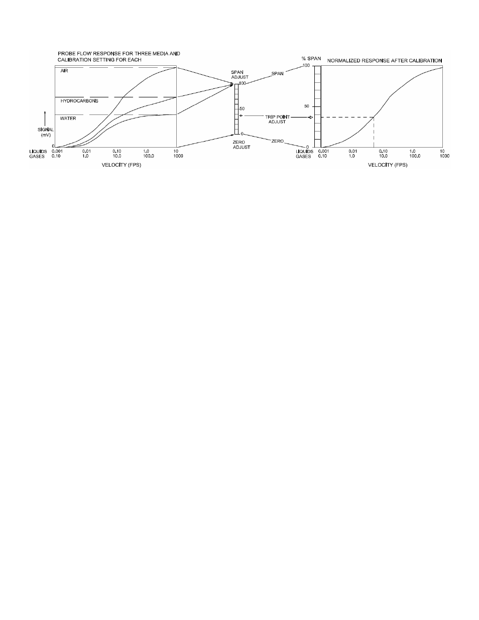
CALIBRATION (Flow Switch)
(Refer to Page #5 for location of controls)
NOTE: For optimum performance, the calibration must be done at actual process temperature and pressure
conditions in gasses, or actual process temperature in liquids.
NOTE: The sensor tips must be perpendicular to the flow direction (see Page #3 – View C-C)
1. Remove the Instrument Enclosure Cover
2. Ensure that the pipeline is filled with fluid and at no or minimum flow.
3. Apply power. Allow the sensor to warm-up for five minutes.
4. Set the “Trip Point Adjust” pot to “0” (fully counterclockwise).
5. Set the “Zero Adjust” pot so that the Red LED just does illuminate. This is a 25-turn pot. If the Green LED is on, turn
the pot counterclockwise. If the Red LED is on, turn the pot clockwise.
6. Toggle the “Zero Adjust” pot back and forth until the trip point is well defined. Leave the Red LED Illuminated.
7. Adjust the liquid or gas flow to maximum velocity for the application. Insure that the flow is homogenous, constant,
and if a liquid – free of bubbles.
NOTE: The maximum allowable flow rate for the unit is 2.5ft/sec (aqueous
liquid), 5 ft./sec (hydrocarbon liquid) or 500ft./sec (gases).
8. Set the “Trip Adjust” pot to 100 (fully clockwise).
9. Set the “Span Adjust” pot so that the Green LED just does illuminate. This is a 25-turn pot. If the Green LED is on,
turn the pot clockwise. If the Red Led is on, turn the pot counter clockwise.
10. Toggle the “Span Adjust” pot back and forth until the switching point is well defined. Leave the Green Led illuminated.
11. If the switch is to be used for flow – no flow, set the “Trip Adjust” pot to 50 and go to Step #14.
NOTE: This
adjustment can be set for tripping points between 10% and 90% of the span from no flow to maximum flow).
12. A more exact flow rate setting may be made by establishing the flow at the desired rate with a separate flow meter
and proceeding to Step #13.
13. Adjust the “Trip Adjust” pot to obtain a trip point as exhibited by the LED Status Lights. If trip on decreasing flow is
desired, set for Red Illumination. If a trip on decreasing flow is desired, set for Green Illumination.
14. Verify that the switch will reset by returning the actual product flow to maximum or minimum flow rates. The
calibration is complete.