Kenco Engineering Thermal Differential Switch User Manual
Page 5
Page 5
4. Pull the power/signal wires through the conduit opening.
5. Connect Power and relay wiring to Terminal Block (TBB) see figure on previous page.
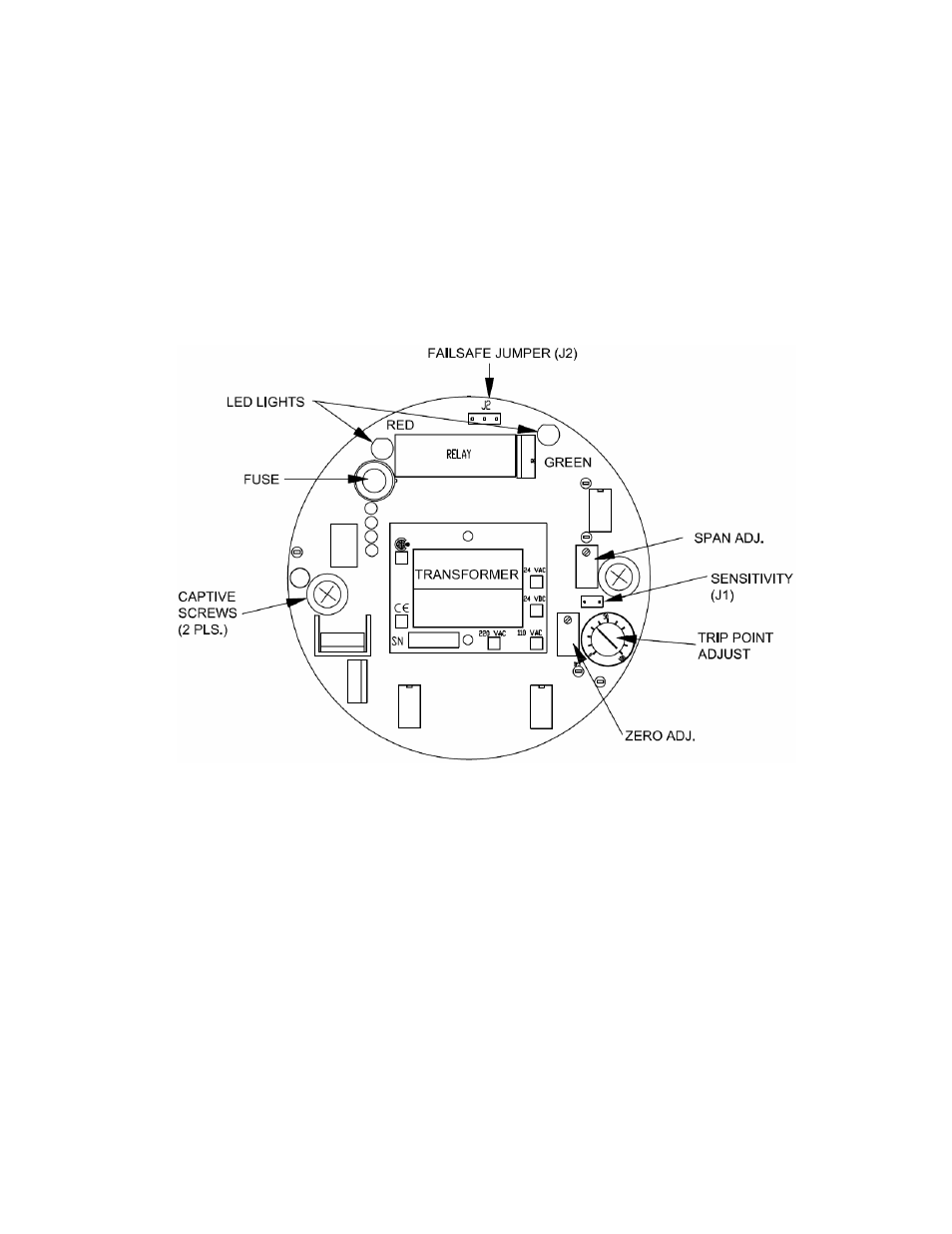
6. Reinstall the Electronic Module and tighten the (2) captive screws.
7. Reinstall the Instrument Enclosure cover.
OPERATIONAL CHECK
After the switch is installed, and the level is below the sensor or there is no flow, perform the following test procedure to
insure proper function.
1. Remove the Instrument Enclosure Cover.
2. Apply power.
3. Verify that either the Red or Green LED is illuminated.
4. If neither LED is on, refer to the Troubleshooting section.
PRE-CALIBRATION
LED States
The Red and Green LED’s indicate the status of the sensor, and are independent of the relay status. When the Red LED
is illuminated, this indicates a Dry (Level) or No/Low (Flow) condition. When the Green LED is illuminated, a Wet (Level)
or High (Flow) condition is indicated.
Jumper Settings
There are (2) jumpers that must be set prior to calibration:
J1 – Model KTDL – There is no J1 Jumper or Pins
Model KTDF – Leave the Jumper in place for Flow Applications; Remove the Jumper if you decide to use this
model for a Level / Interface Application