HF scientific Micro200BW Turbidimeter - 0 -1000 NTU User Manual
Page 39
Page 25
MICRO 200 BW 0 - 1000 NTU (5/05)
Rev. 3.1
B. START UP
Before placing the MICRO 200 BW on line we recom-
mend that you standardize the instrument. The follow-
ing sections describe the required procedures.
1. Indexing
The United States Environmental Protection Agency
(U.S. EPA) recommends that cuvettes used for instru-
ment calibration or sample measurement be indexed.
To comply with U.S. EPA standards, the MICRO 200
BW includes an Indexing Ring for quick and repeatable
indexing of the refernce standard.
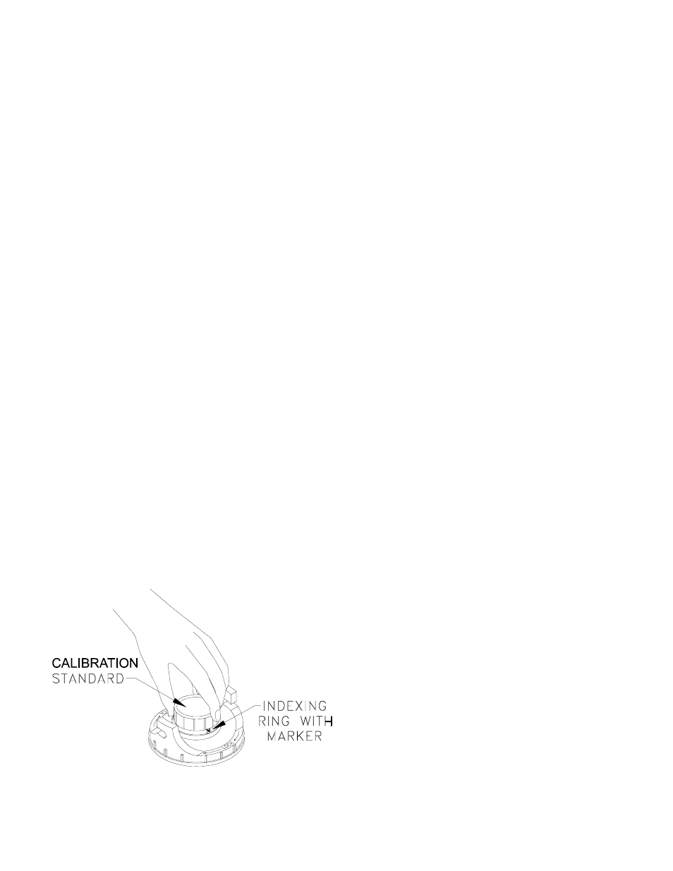
To index the calibration standard you must be in the
calibration menu. Observe the top center (current
frequency) reading while performing the following steps:
a. Slowly rotate the standard, inside the optical well,
one complete revolution (360°). While rotating the
standard slowly, observe the measured turbidity
and locate the position of the cuvette having the
lowest reading.
b. With the calibration standard positioned at the
location having the lowest turbidity reading, install the
Indexing Ring over the cap on the standard so that the
pointer of the Indexing Ring faces directly forward.
When using the standards in the future, always insert the
standard so that the pointer of the indexing ring faces
forward. Slowly rotate the standard back and forth
about 5° to find the lowest point. The standard is now
indexed and ready for use.
Figure 9 shows a calibration standard being indexed.
NOTE: This Calibration Standard is only Indexed to
the Turbidimeter for which it was aligned.
Figure 9
Reference Standard Indexing
2. Standardizing
The reference standard (cuvette) supplied with the
MICRO 200 BW is a pure liquid sealed in glass. It has
a value of 0.02 NTU.
Standardization is performed in the calibration menu
see page 18 for more details. While in the calibration
menu perform the following operations:
a. Place the Reference Standard in the Optical Well.
b. Index the Reference Standard as previously de-
scribed.
c. Allow a few seconds for the standard to stabilize.
d. Press the F1 button to accept the frequency.
NOTE: This operation “calibrates” the .02 NTU refer-
ence standard in the range of interest. If both
ranges maybe used this operation should be
performed on both ranges.
CAUTION: Avoid scratching the surface of the cu-
vette. Keep the cuvette surface clean and
free of dust. A scratched or dirty and
dusty cuvette will cause analysis error.
For instructions (See: V. ROUTINE
MAINTENANCE).
IV. ROUTINE OPERATION
A. CONTINUOUS MONITORING FLOW
THROUGH UNIT
The standard flow through unit supplied with the in-
strument is designed to operate at pressures up to a
maximum of 60 p.s.i. (414 kPa or 4.22 kg/cm
3
) and
temperatures to a maximum of 122° F (50° C) fluid
temperature. Flow rates through the unit can be ad-
justed from 0.5 gpm (200 ml/min) to a maximum of
approximately 1.5 gpm (5.7 liters/minute). The speed
of sensing turbidity changes will depend on the length
of the take-off line, the diameter of the take-off line,
and the flow rate or velocity through the take-off line.
By using a high flow rate and keeping the lines small,
approximately 3/16 inch (4.8 mm) I.D. and relatively
short length, the response time is kept to a minimum.
Consult HF scientific, inc. when unusually long con-
nections are required.
Depending on the type of fluid being monitored, a
pressure drop through the line can cause gas or air to
come out of solution and form bubbles which will
create errors in the turbidity measurements. This can be
prevented by creating a slight back pressure on the