HF scientific Micro200BW Turbidimeter - 0 -1000 NTU User Manual
Page 22
Page 8
MICRO 200 BW 0 - 1000 NTU (5/05)
Rev. 3.1
WARNING: Do not restore power until the access
cover has been replaced and secured.
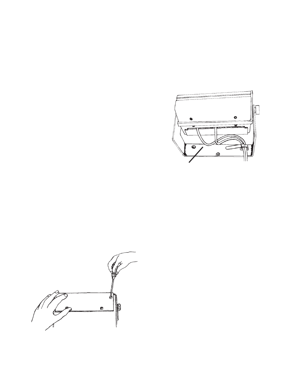
When routing the cabling for the following
sections, allow enough excess cable length
to swivel the analyzer upside down. Note
that a cable strap is provided on the mount-
ing bracket. Refer to figure 5 for suggested
cable routing. Do not overtighten the four
captive screws when replacing cover.
Figure 5
Cable Routing
1. Cable & Cord
Interconnecting Cable: The standard interconnecting
cable between the analyzer and the turbidity sensor is
6 feet (1.83 meters) in length (Catalog No. 20853). This
length may be decreased without affecting instrument
performance. For longer cable lengths consult HF
scientific, inc.
WARNING: Ensure that power to the analyzer is
removed prior to connecting or dis-
connecting the sensor.
2. Analyzer Power
The power cord (120V) provided is 6 feet (1.83 meters)
long. The analyzer power requirement is 40 VA at
either 120 VAC or 240 VAC. The voltage setting of the
analyzer can be determined by removing the access
cover and looking at the fuse cartridge, just to the left
of the power cord receptacle. The voltage printed next
to the two triangles that point toward each other indicate
the selected voltage. To change the input voltage first
remove the power cord. The fuse cartridge can be
removed by prying upwards using a flat blade screw-
driver in the slot provided. Pull the cartridge out, invert
and then reinsert. Refer to figure 6 on page 9. To replace
a blown fuse remove the fuse cartridge as in figure 6 on
page 9. Replace only the fuse for your selected voltage.
The triangle on the fuse cartridge points to the fuse for
instrument. The desiccant pouch is designed to have a
long life; however, replacement of the desiccant pack
will be required from time to time. To determine the
condition of the desiccant, check the included humidity
indicator card. If required, a new foil sealed desiccant
pouch and indicator card are available from HF scien-
tific inc. part #21555R.
It is essential that all enclosure seals be maintained. The
emergency drain and o-rings that are supplied with each
new instrument form part of the instrument humidity
seal. Inspect these items each time the desiccant pouch
is replaced. Replace any parts found to be defective.
D. ANALYZER CONNECTIONS
All connections are reached by removing the access
cover. Heed all warnings and precautions prior to
removal.
WARNING: Before removing access cover disconnect
all power from the MICRO 200 BW ana-
lyzer.
1) Unplug the instrument or
2) Turn off the power at the circuit breaker.
3) Remove power to alarm contacts if greater than 30
VAC is connected for external operations.
To remove the access cover (refer to figure 4):
1) Loosen the two analyzer clamping knobs.
2) Swivel the analyzer top forward, such that the back
is now facing you.
3) Re-tighten the two analyzer clamping knobs.
4) Loosen the 4 captive screws.
5) Remove access cover.
Figure 4
Access Cover Removal
→
→→
→→
Extra Cable