Shaft storage cradle, Gap gauge, photo safety sensor – GBC 64C User Manual
Page 19
Page 5-5
SPIRE II Series – Installation and Operating Instructions
s
haFt
s
toraGe
c
radle
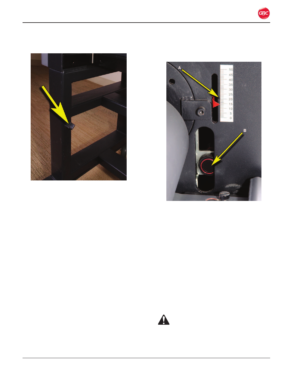
Figure 14. Shaft Storage Cradle on Back of the Laminator.
Use to Shaft Storage Cradles to store shafts that are
not in use.
G
ap
G
auGe
, p
hoto
s
aFety
s
ensor
Figure 15. Components on right side of Feed Table.
a. G
ap
G
auGe
The Gap Gauge indicates the amount of gap
between the Main Rollers. Use the Gap/Pressure
Crank to adjust the gap.
B. p
hoto
s
aFety
s
ensor
The Photo Safety Sensor helps prevent
entanglement, entrapment, and inadvertent contact
with the rollers. The Sensor is located on the right
side of the machine, in front of the Bottom Main
Roller. Its reflector is at the opposite end of the Feed
Table. The Sensor stops the machine when a hand
or object blocks the invisible beam if you are not
using the Footswitch.
To return to normal operation after the obstruction
has been cleared, press
RUN.
WARNING: Using the Footswitch overrides the
Photo Safety Sensor and the speed drops to 3 ft. (1
meter) per min. When the Footswitch is released, the
laminator stops.