Green tube connection, Black tube connection, Final filter installation – Watts PWRO4ZRO User Manual
Page 6: Check air pressure in the tank, Tank ball valve installation, Step 5, Step 6, Step 9, Step 7, Step 8
6
STEP 5
Green Tube Connection
Step A – Locate green tube attached to the
RO Module . Insert the open end of
the green
1
⁄
4
" tube into the open
1
⁄
4
"
quick-connect fitting on the Adapt-
A-Valve™ making sure the tube is
pushed in all the way to the tube
stop .
Step B – Connect the green tube from the RO
module to the Adapt-A-Valve™ that
is connected to the cold water angle
stop valve . Leave enough tube so it is not kinked and cut
the tube to the desired length .
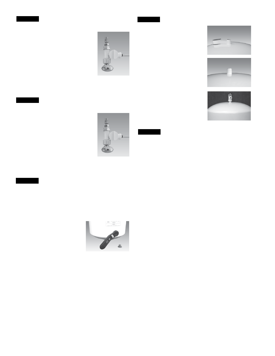
STEP 6
Black Tube Connection
Step A – Locate black tube attached to the
RO Module . Insert the open end of
the black
1
⁄
4
" tube into the open
1
⁄
4
"
quick-connect fitting on the Adapt-
A-Valve™ making sure the tube is
pushed in all the way to the tube
stop .
Step B – Connect the black tube from the RO
module to the Adapt-A-Valve™ that
is connected to the hot water angle
stop valve . Leave enough tube so it is not kinked and cut
the tube to the desired length .
STEP 9
Final Filter Installation
Step A – Locate
3
/
8
" blue tubing in parts bag . The final polishing filter
is clipped onto the top of the membrane housing . Connect
one open end of
3
/
8
" blue tubing to the quick-connect fitting
labeled "Faucet" located on the final polishing filter . Make
sure that the tube is pushed in all the way to the tube stop .
Step B – Connect the other end of the
3
/
8
" blue tubing connected to
the in-line filter to the quick-connect fitting located on the
faucet shank .
Note: A connection to a refrigerator / ice maker may be tee’d
into this blue tube and should be spliced in between the final
filter and the RO faucet.
STEP 7
Check Air Pressure in the Tank
Note: Check air pressure when tank is empty of water!
Check air pressure in the storage tank when you notice a de-
crease in available water from the RO system. Air can be added
with a bicycle pump using the schrader valve that is located on
the lower side of the tank behind the blue plastic cap.
Step A – Turn off the incoming water
supply to the RO by turning the
knob on the Adapt-A-Valve™
clockwise until it stops . (Follow
the green tube away from the
RO system to find the Adapt-A-
Valve™ .)
Step B – Open the RO Faucet and allow water to drain from the tank
until it is completely empty .
Tip: When water from the RO faucet slows to a trickle, with the
faucet still in the open position, you may add air to the tank to
purge any left over water. This will ensure that the tank is com-
pletely empty.
Step C – Once all water in the tank is purged, check air pressure us-
ing an air pressure gauge, it should read between 5 - 7psi .
(Digital air pressure gauge is recommended)
Step D – Follow startup procedure on Page 7 .
Step A – Teflon
®
tape must be applied
in a clockwise direction . Wrap
(4 to 8 turns) around the male
pipe threads (MPT) on the
stainless steel fitting on top of
the tank .
Step B – Thread the Quick-Connect
ball valve (supplied in the
parts bag) onto the stainless
steel connector on the tank .
Caution: Do not Teflon
®
tape the
plastic elbow threads as this may cause
leaks .
Tank Ball Valve Installation
STEP 8
Teflon
®
is a registered trademark of E .I . Dupont de Nemours & Company .