Reverse osmosis module mounting, Adapt-a-valve™ installation, Configuration for – Watts PWRO4ZRO User Manual
Page 5: Configuration, Step 4, Step 2, Step 3
5
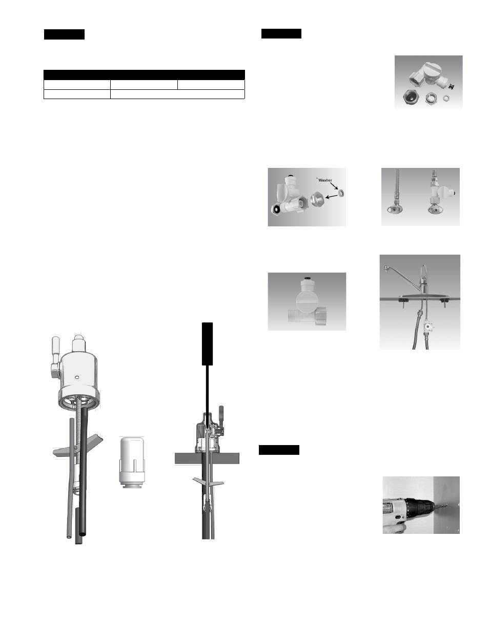
STEP 4
Reverse Osmosis Module Mounting
Step A – Determine best location for the
RO module to be mounted to
allow for future system main-
tenance . The parts bag has 2
self-tapping screws . Using an
electric drill with a Phillips bit,
screw them into the cabinet
wall 6" apart and 16" from the
bottom of the cabinet .
Note: Do not cut any RO system tubes at this time
STEP 2
Watts Chrome Top Mount
Faucet Installation
Gather and identify the faucet pieces.
Step A - Remove faucet base and faucet spout from their respective
plastic bags . From above the sink, feed the faucet tubing
& toggle bolt down through the 1¼" mounting hole in the
sink . Ensure that the soft rubber gasket has the protec-
tive white paper removed from both sides and is uniformly
positioned in between the base of the faucet and the top of
the sink .
Step B - Align the faucet base so that the handle is on the right side
and the base is sitting flush on the sink top . Using a phillips
head screwdriver, turn the screw located down the hole
where the spout will be installed, clockwise until the toggle
bolt secures the faucet base snug onto the sink top .
Step C - Once the faucet base is securely fastened to the sink top,
insert the faucet spout into the faucet base until it is fully
seated . Turn the handle up (away from you) to the “OFF”
position .
Step D - Connect the loose end of the
3
⁄
8
" blue plastic tubing from
the faucet to the
3
⁄
8
" plastic fitting from the final inline filter .
MiniMuM
MaxiMuM
Mounting Hole Size
1"
1
1
⁄
4
"
Torque on Toggle Bolt
5 lb.in. (max)
Adapt-A-Valve™ Installation
Verify contents prior to installation:
( 1 ) - Plastic Adapt-a-Valve™ & Black Collet
( 1 ) - Brass Adapter no washer
( 1 ) - Brass Adapter with black washer
( 1 ) - White rubber washer
Water supply line to the system must be from the cold water
supply line only. Hot water will severely damage your system.
WARNING: Do not use Teflon tape with the Adapt-A-Valve™.
For
3
⁄
8
" Configuration
For
1
⁄
2
" Configuration
Step A - Turn off the cold water supply to the faucet by turning the
angle stop valve completely off .
Step B - Open cold water sink faucet to relieve pressure .
Step C - Choosing the configuration that fits your plumbing, at-
tach the Adapt-A-Valve™ as illustrated in the four photos
above .
STEP 3
Hot
Supply
Cold
Supply
Hot
Supply
Cold
Supply
(With Brass Fittings)
* Insert White Washer
(Without Brass Fittings)
1
⁄
2
" Configuration